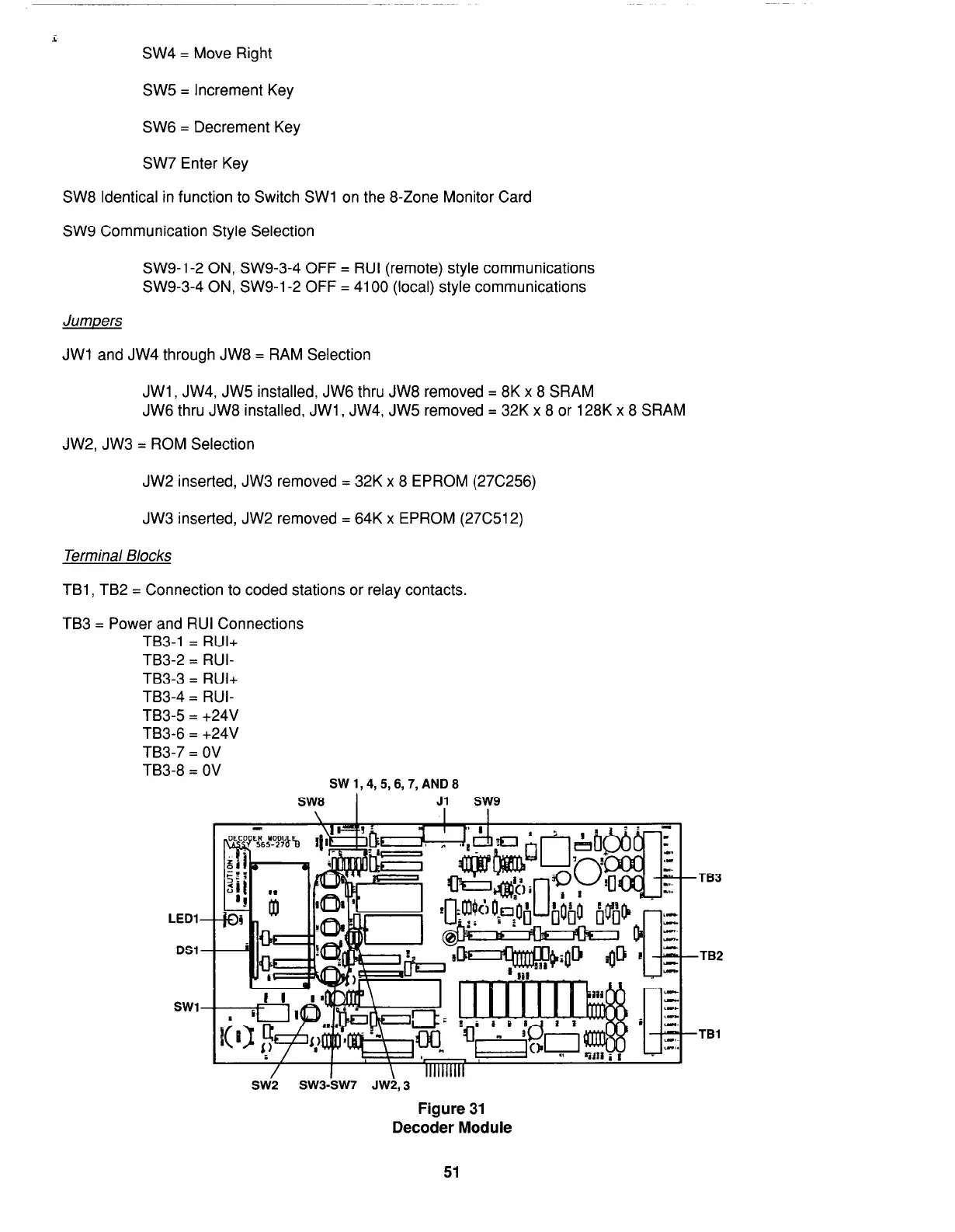
EasyManuals Logo

Simplex 4100 Service Instructions

Simplex 4100
98 pages
To Next Page IconTo Next Page
To Previous Page IconTo Previous Page
Page #61 background imageLoading...
Page #61 background image
i
SW4 = Move Right
SW5 = Increment Key
SW6 = Decrement Key
SW7 Enter Key
SW8 Identical in function to Switch SW1 on the 8-Zone Monitor Card
SW9 Communication Style Selection
SW9-1-2 ON, SW9-3-4 OFF = RUI (remote) style communications
SW9-3-4 ON, SW9-1-2 OFF = 4100 (local) style communications
Jumpers
JWl and JW4 through JW8 = RAM Selection
JWl, JW4, JW5 installed, JW6 thru JW8 removed = 8K x 8 SRAM
JW6 thru JW8 installed, JWl , JW4, JW5 removed = 32K x 8 or 128K x 8 SRAM
JW2, JW3 = ROM Selection
JW2 inserted, JW3 removed = 32K x 8 EPROM (276256)
JW3 inserted, JW2 removed = 64K x EPROM (27C512)
Terminal Blocks
TBl , TB2 = Connection to coded stations or relay contacts.
TB3 = Power and RUI Connections
TB3-1 = RUI+
TB3-2 = RUI-
TB3-3 = RUI+
TB3-4 = RUI-
TB3-5 = +24V
TB3-6 = +24V
TB3-7 = OV
TB3-8 = OV
SW1,4,5,6,7,AND8
TB3
LED1
DSl
TB2
SW1
TBl
/
SW2
sw3-Jsw7 JW1,3
IIIIIIIIII
Figure 31
Decoder Module
51
firealarmresources.com

Table of Contents

Other manuals for Simplex 4100

Questions and Answers:

Question and Answer IconNeed help?

Do you have a question about the Simplex 4100 and is the answer not in the manual?

Simplex 4100 Specifications

General IconGeneral
TypeFire Alarm Control Panel
ManufacturerSimplex
Model4100
Network CapabilityYes
AddressableYes
Power Supply120/240 VAC, 50/60 Hz
DisplayLCD
Annunciator SupportYes
Battery BackupYes
Releasing CapabilityYes
Max DevicesDepends on configuration
Max Notification Appliance Circuits (NAC)Varies with configuration
Max Releasing CircuitsVaries with configuration
Max Remote AnnunciatorsVaries with configuration
Communication PortsMultiple
Operating Temperature32°F to 120°F (0°C to 49°C)
Humidity RangeUp to 93% RH, non-condensing
NAC Outputs4 (expandable)
NetworkingYes

Related product manuals