TB3 JW3.4.5&6 JW2 P3
P2 Pl P9 P8
PlO F2 P6 P7 TBl
F3
LED1
JW8 JWl Fl F4 Pll F5 P4
P5 TB2
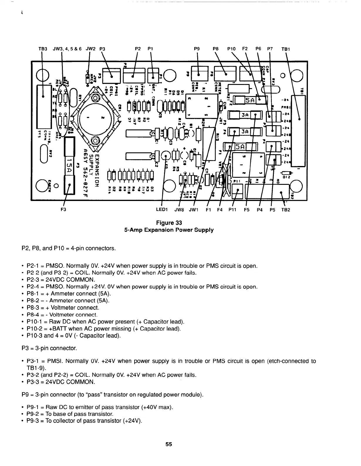
Figure 33
5-Amp Expansion Power Supply
P2, P8, and PlO = 4-pin connectors.
l
P2-1 = PMSO. Normally OV. +24V when power supply is in trouble or PMS circuit is open.
l
P2-2 (and P3-2) = COIL. Normally OV. +24V when AC power fails.
l
P2-3 = 24VDC COMMON.
l
P2-4 = PMSO. Normally +24V. OV when power supply is in trouble or PMS circuit is open.
l
P8-1 = + Ammeter connect (5A).
l
P8-2 = - Ammeter connect (5A).
l
P8-3 = + Voltmeter connect.
l
P8-4 = - Voltmeter connect.
l
Pl O-l = Raw DC when AC power present (+ Capacitor lead).
l
Pl O-2 = +BATT when AC power missing (+ Capacitor lead).
l
Pl O-3 and 4 = OV (- Capacitor lead).
P3 = 3-pin connector.
l
P3-1 = PMSI. Normally OV. +24V when power supply is in trouble or PMS circuit is open (etch-connected to
TBl-9).
l
P3-2 (and P2-2) = COIL. Normally OV. +24V when AC power fails.
l
P3-3 = 24VDC COMMON.
P9 = 3-pin connector (to “pass” transistor on regulated power module).
l
P9-1 = Raw DC to emitter of pass transistor (+4OV max).
l
P9-2 = To base of pass transistor.
l
P9-3 = To collector of pass transistor (+24V).
55