99
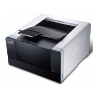
2. Pass through the figure`2` of ‘A’ and insert a bump on the floor `C` into the hole `2`
of B.
3. Rotate ‘C’ in CW so that the arrow shape of `C` at the bottom side should point and
fit into + groove around the hole `2` of B.
4. Tighten screws at 4 locations and remove 'C'.
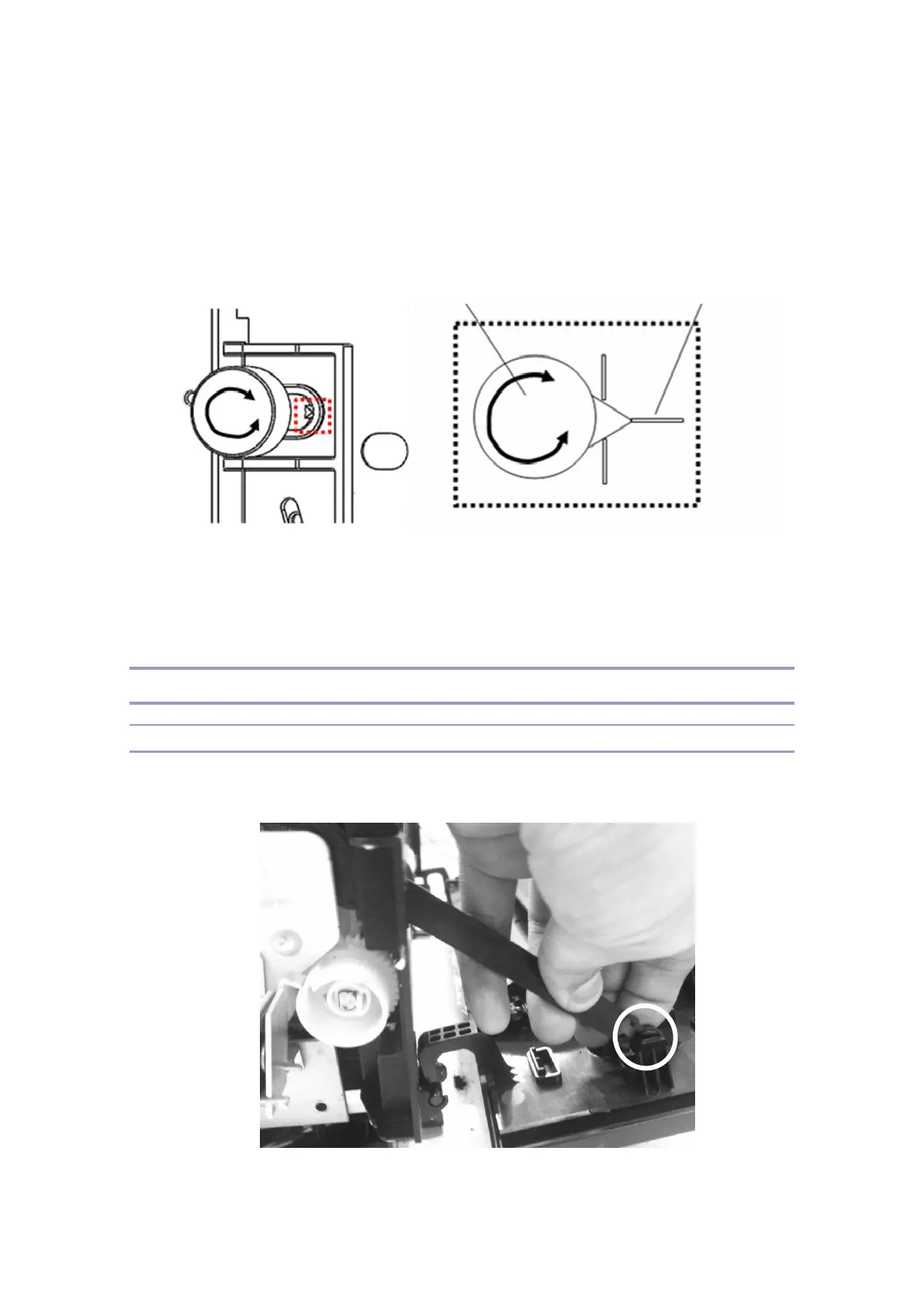
Main Drive Assy Unit
Removing Main Drive Gear Unit
1. Remove the links connected to the front cover(pull them out to the insdie of the
machine.).
 Loading...