Installation and start-up
34 / 76 Sintratec S1 BA_S1_en 1.1
Pos: 125 /Sintratec /Überschrift en/2. Ebene/E - H /Erste Inb etriebnahme @ 3\ mod_146649 3554903_655 6.docx @ 9650 @ 2 @ 1
6.10 Initial start-up
Pos: 126 /Sintratec /Kap./Montag e und Anschlüss e/Inbetriebnah me, erste Ei nschalten S1 @ 3 \mod_147 0654907747_65 56.docx @ 1051 5 @ @ 1
Following the installation procedure, the device can be put into operation.
1. Move the main switch to the ON position.
2. Use the ON/OFF button to switch on the device (white lamp lights up).
3. Start "Sintratec Central" at the computer connected to the device.
Pos: 127 /Sintratec /Kap./Montag e und Anschlüss e/Inbetriebnah me, erste @ 3\ mod_146 6153406851_6556.d ocx @ 9533 @ @ 1
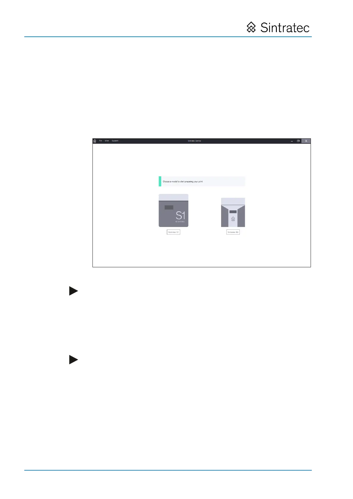
At the computer, the connected device is automatically detected and is ready for
operation.
Fig.
: "Sintratec Central" start screen
Note
In case the device has not been automatically detected, proceed as follows:
– Ensure that the USB cable is connected to both the computer and the device.
– Ensure that the device is on.
– Ensure that the latest USB driver available from the Sintratec Academy has
been installed. The Windows Device Manager can be used to check whether
the device has been correctly identified. It must be listed as "Sintratec Kit/S1"
under "Universal Serial Bus Devices".
Note
We recommend that, directly after putting the device into operation, you produce
the sample print object as the first print object. Then any calibration that is
required can be carried out.
The printing process is described in the "Operation" chapter below, with the
sample print object being used as an example for this purpose.
Pos: 128 /Allge mein/+++++++++ +++ Neues Kapi tel +++++++++ +++ @ 0\ mod_1414754200 269_0.docx @ 6973 @ @ 1