ALC404 LIGHTING TOWER CONTROLLER USER MANUAL
ALC404 Lighting Tower Controller 2018-11-06 Version 1.1 Page 33 of 83
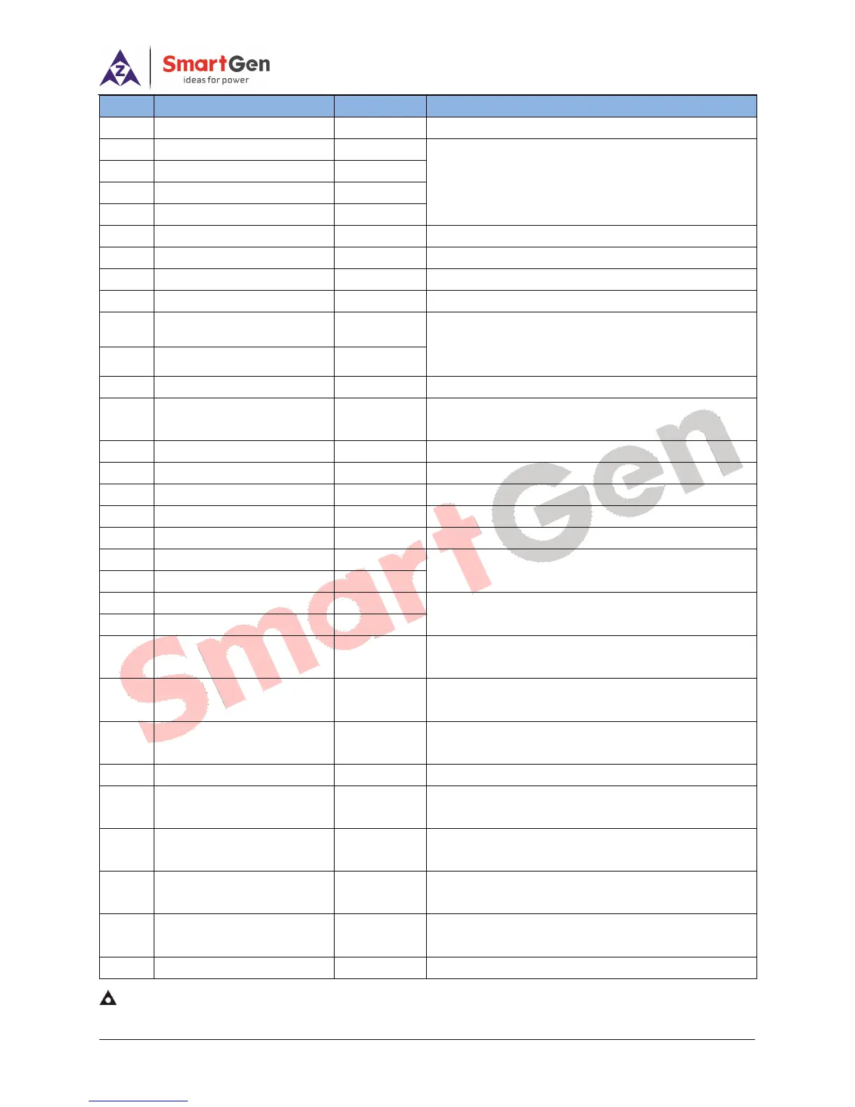
of volt free relay; external connect with DC voltage.
Separately combined with terminal No. 8 as
normally open contactor of relay with rated current
1A (voltage free output). Recommend enlarging the
capacity of relay according to the load.
It is programmable sensor.
It is programmable sensor.
It is programmable sensor.
Internal connect with B-, sensor common ground.
120Ω resistance is paralleled with CAN H and CAN
L. Transceiver is non-isolated and shielded wire is
recommended.
Connect to speed sensor. Internal has connected
with B-.
Digital input port, which connected B- to activate.
Digital input port, which connected B- to activate.
Digital input port, which connected B- to activate.
Digital input port, which connected B- to activate.
Digital input port, which connected B- to activate.
Connect to the output port of Hall DC 4-20mA
sensor (DC generator current).
Connect to output port of DC generator.
Genset U-phase Volt.
Monitoring Input
Connect to U-phase output port of genset
(recommend 2A fuse).
Genset V-phase Volt.
Monitoring Input
Connect to V-phase output port of genset
(recommend 2A fuse).
Genset W-phase Volt.
Monitoring Input
Connect to W-phase output port of genset
(recommend 2A fuse).
Connect to N-wire output port of genset.
CT A-phase Monitoring
Input
Externally connect to secondary coil of current
transformer (max. 5A).
CT B-phase Monitoring
Input
Externally connect to secondary coil of current
transformer (max. 5A).
CT C-phase Monitoring
Input
Externally connect to secondary coil of current
transformer (max. 5A).
Common ground; Connect with negative of starter
battery.
Communicate with PC software.
NOTE: USB port in the rear of controller is communication port, which can realize controller programming and monitoring
functions via PC software.