ALC404 LIGHTING TOWER CONTROLLER USER MANUAL
ALC404 Lighting Tower Controller 2018-11-06 Version 1.1 Page 32 of 83
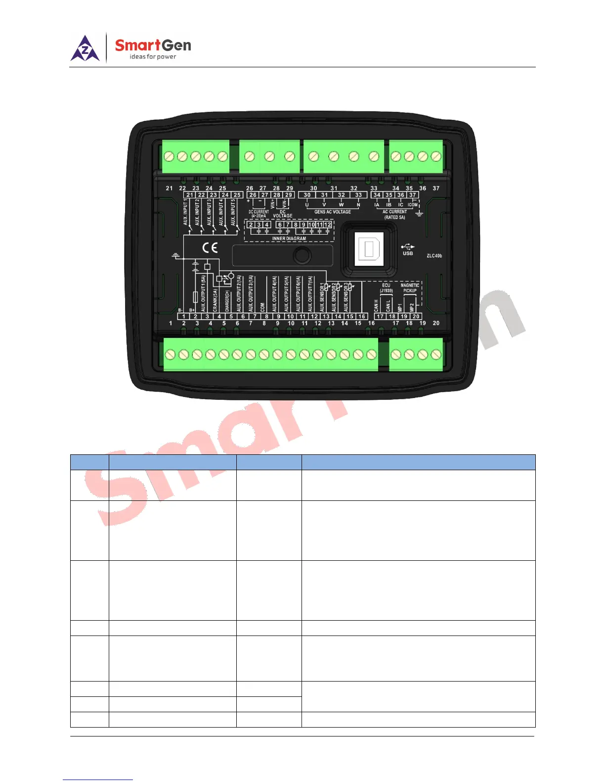
6 WIRING CONNECTION
ALC404 controller’s rear is as following:
Fig.2 - ALC404 Controller Rare Panel Diagram
Table 17 - Terminal Connection Description
DC power negative input and external connected
with negative of starter battery.
DC power positive input and external connected
with positive of starter battery. If the length is above
30m, double wires need to be paralleled and 20A
fuse is recommended.
B+ output is supplied by terminal No.2, rated 5A. If
the fuel relay output needs to be connected, users
can configure ―Output 1 Settings‖ in ―Relay Output
Ports Setting‖ page.
B+ output is supplied by terminal No.2, rated 5A.
Connected with charger’s D+ (WL) terminal. If no
this terminal in charger, this terminal is hanging in
the air. .
Terminal No. 9~No.12 correspond to common port