ALC404 LIGHTING TOWER CONTROLLER USER MANUAL
ALC404 Lighting Tower Controller 2018-11-06 Version 1.1 Page 82 of 83
12 INSTALLATION
12.1 FIXING CLIPS
─ Controller is panel built-in design; it is fixed by clips when installed.
─ Withdraw the fixing clip screw (turn anticlockwise) until it reaches proper position.
─ Pull the fixing clip backwards (towards the back of the module) ensuring two clips are inside their
allotted slots.
─ Turn the fixing clip screws clockwise until they are fixed on the panel.
Note: Care should be taken not to over tighten the screws of fixing clips.
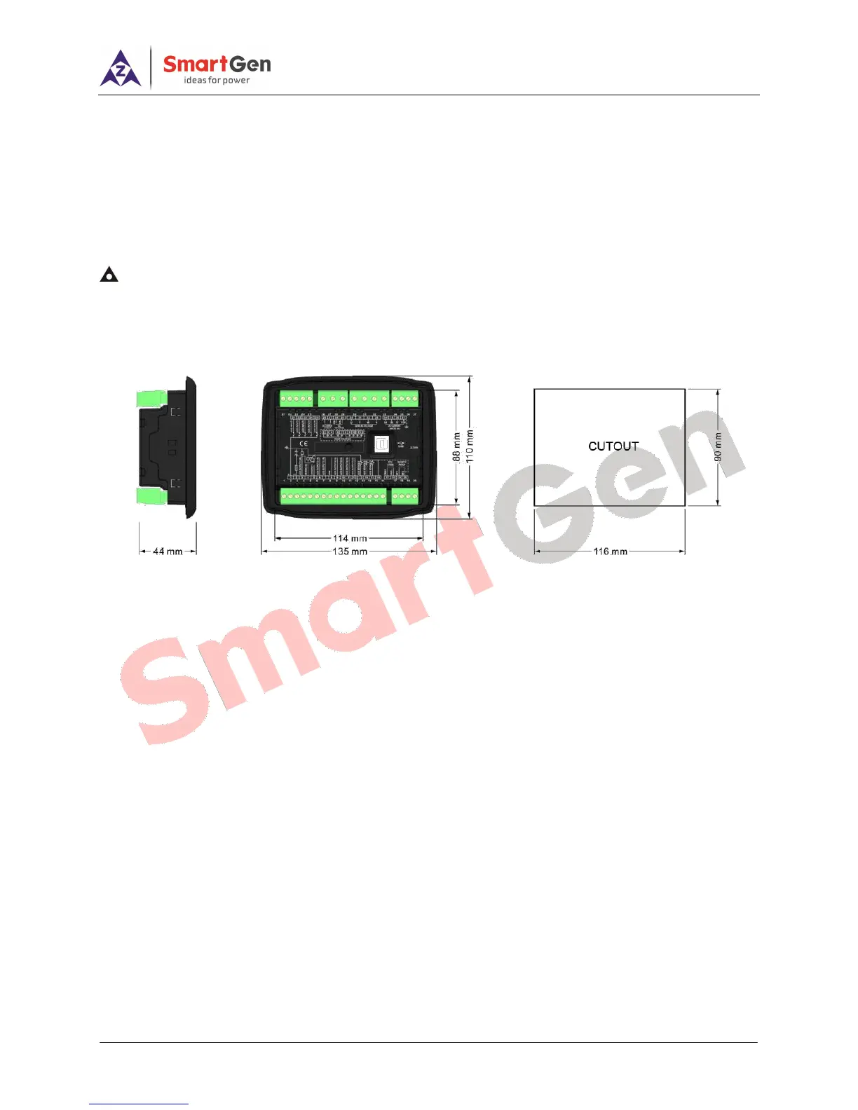
12.2 OVERALL AND CUTOUT DIMENSIONS
ALC404 controller is penal built-in design, and fixed by clips when installed. Overall dimension and
cutout dimension are as follows,
Figure 9 - Overall Dimensions
12.3 WIRING CONNECTION DESCRIPTION
Battery Voltage Input: ALC404 controller can suit for widely range of battery voltage DC (8~35) V.
Negative of battery must be connected with the engine shell. Diameter of wire that connects from power
supply to battery must be over 1.5mm
2
. If floating charge configured, please firstly connect output wires of
charger to battery’s positive and negative directly, then, connect wires from battery’s positive and negative
to controller’s positive and negative input ports in order to prevent charge disturbing the controller’s normal
working.
Speed Sensor Input: Speed sensor is the magnetic equipment which be installed in starter and for
detecting flywheel teeth. Its connection wires to controller should apply for 2 cores shielding line. The
shielding layer should connect to No. 20 terminal in controller and the else two signal wires are connected to
No.19 and No.20 terminals in controller. The output voltage of speed sensor should be within (1~24) VAC
(effective value) during the full speed. 12VAC is recommended (in rated speed). When install the speed
sensor, let the sensor is spun to contacting flywheel first, then, port out 1/3 lap, and lock the nuts of sensor at
last.
Output and Expand Relays: All outputs of controller are relay contact output type. If need to expand
the relays, please add freewheel diode to both ends of expand relay’s coils (when coils of relay has DC
current) or, increase resistance-capacitance return circuit (when coils of relay has AC current), in order to
prevent disturbance to controller or others equipment.
AC Current Input: Current input of ALC404 controller must be connected to outside current transformer.
And the current transformer’s secondary side current must be 5A. At the same time, the phases of current