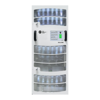
Sirius 800 www.snellgroup.com Power Supplies
Issue 1 Rev 1 Page 19 © 2014 Snell Limited
3.5 Power Distribution
The power supply shelves provide 48 V DC for distribution to the entire frame. All router
modules (inside the frame) have on-board DC to DC converters to locally supply the required
voltages. A single Green LED on the front edge of each module indicates that all is working
correctly. This arrangement provides simple power distribution, as well as effective power
de-coupling between modules.
3.6 Power and Alarm Connections to the Sirius 800 Frame
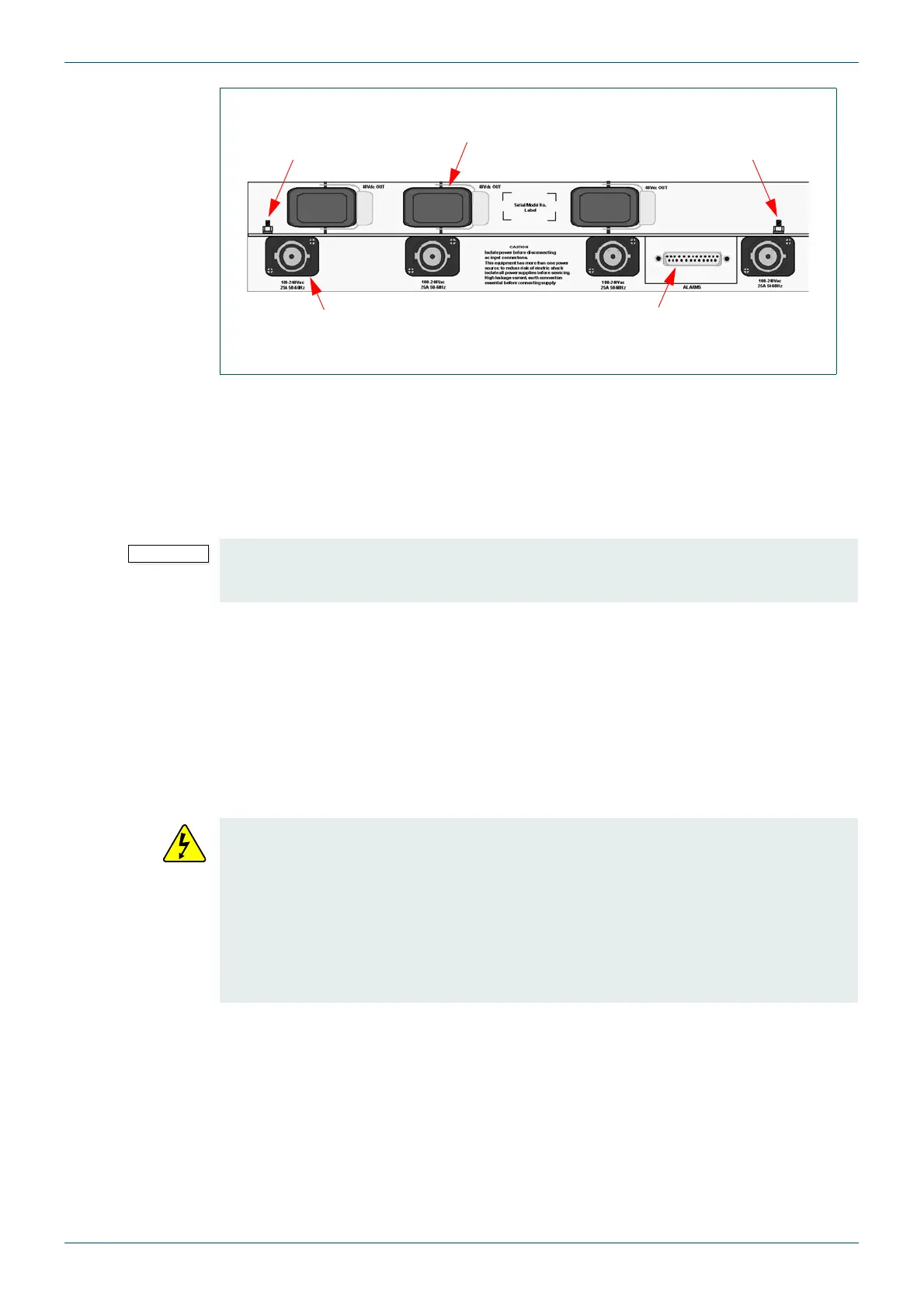
The Sirius 800 is powered by up to three 2RU power supply Shelves depending on the router
configuration and mains voltage (see the appropriate Sirius 800 Installation and Quick Start
guide for details). The power supply shelves each have up to four PowerCon AC input
connectors (see Fig 4.).
Each power supply shelf has three 48 V DC power connectors, only two connectors from
each power supply shelf are used to power the Sirius 800. The cover on the unused 48 V DC
socket must be left on the power shelf.
Up to two power supply alarm cables (636028) are supplied with the Sirius 800 depending on
the number of power supply shelves fitted. Connect each power supply shelf to the router
alarm rear panel using the 25-Way connector. The alarm signals send a warning to the Door
PC, and via external GPIs or an external Workbench system if there is a power supply failure.
The power supply alarm cable(s) are supplied by Snell and can be ordered as either
2.5 meter cables or 8 meter cables.
Fig 4. Power Supply Shelf Rear Panel
Functional Earth
Point, see section
2.7.2
PowerCon AC Input
Connectors x4
48 V DC power
connectors
Protective Earth
Point, see
section 2.7.1
25 Way D Type
Alarms Connector
The Fan Out Control modules provide power to all fan modules. At least one Fan Control
module must be present or the fans will stop, which will cause the Sirius 800 to quickly
overheat. To prevent the fans from stopping, there are two Fan Control modules.
• The power supply shelves MUST be isolated from the AC supply by means of the
external distribution switch/circuit breaker before connecting or disconnecting the
48 V DC power cables. This is required because the “PowerCon” connectors are
not suitable for isolating current.
• This equipment has more than one power source, to reduce risk of electric shock
isolate all power supplies before servicing.
• High leakage current, Protective Earth connection essential before connecting
supply (see section 2.7.1).