Sirius 800 www.snellgroup.com Crosspoint Faults and Replacement
Issue 1 Rev 1 Page 73 © 2014 Snell Limited
3. Replace the failed audio crosspoint module with a replacement working crosspoint
module.
4. The replacement audio crosspoint module is automatically tested and the Fault
Present indicator will change back to Green if the replacement is fully working.
5. Touch the Fault Fixed button to move all of the routes from the crosspoint module to
the fixed audio crosspoint module.
6. The Audio Crosspoint Matrix Status screen should now return to its working state
(see Fig 36. on page 70 for button and parameter locations):
• Fail Found indicator - Green
• Fault Present indicator - Green
• First Failure Detected - Failed Incoming Stream and Failed Outgoing Stream
will be reset to 0
• XpntCardNone - Yellow
• XpntCardRedundant - Grey
• XpntCardMain - Grey
7.4.1.2 Replacing an Audio Crosspoint Module without using the Door PC
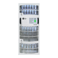
1. Open the router door and then open the fan door to locate the audio crosspoint
modules. Identify the faulty audio crosspoint module, the “Route Fail” LED will be
flashing Red (see section 7.3.1 for the location of the status LEDs).
2. Press the Reset button on the failed audio crosspoint module (Fig 36. on page 70) so
that the working crosspoint module uses its own audio system clock.
CLK Master LED = On for the working audio crosspoint module, see section 7.3.1 for
the location of the “CLK Master” LED.
3. The faulty audio crosspoint module can be hot swapped for a working audio
crosspoint module without causing any disturbance to audio on the router.
4. Close and secure the fan door and router door.
• The fan assembly should be placed back into the closed position as soon as
possible after opening, as this ensures correct ventilation of the frame. Failure to
do this will result in failure.
• In practice the maximum time that a fan assembly can be left open will depend on a
number of factors such as; ambient temperature, frame loading, crosspoint
routings, etc. To ensure correct operation under all conditions the fan assemblies
should be left open for no more than 4 minutes at a time.
• Take care not to trap any cables when opening and closing the fan door.