17
v1.02
Admin and Installation Guide M900 Setting up
1. Mark the centers of the two holes on the wall or pillar. The centers have to be 60 mm (2.3622")
apart horizontally.
2. Drill the holes and insert the wall anchors flush to the wall.
3. Screw in the screws as shown in Fig. 2, above.
4. Place the two holes on the back of the device over the screws on the wall so that the LED is at the
bottom edge of the device.
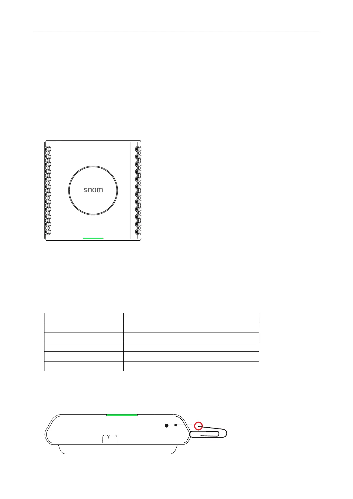
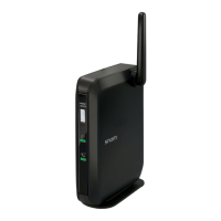
User interface of the unit
Fig. 1
LED status indicator
At the bottom of the front of the unit there is a multicolored LED for status signaling (Fig. 1). After the
PoE cable—or, if PoE is not available, the Ethernet cable and the power supply—is connected to the
unit, the orange LED will begin to blink, indicating that the unit is booting. When the solid green LED
comes on, the unit is connected to the network and is operational.
LED indicator System state
Solid green Operational
Blinking orange Booting
Blinking red Network or registration failure
O No power
Green, flashing rapidly Software update in progress
Reset key
The reset key on the bottom of the unit is used to return the settings to factory defaults. To perform a
factory reset, press the key with an object like the end of a paper clip for at least 10 seconds.
Fig. 7