When powered for the rst time the controller will prompt the user to congure using the wizard.
To access the wizard input code 1000 then the conguration will go as follow:
SMART WIZARD CONFIG:
Foradvanced conguration go to parameters menu.
Language Source configTime & date
Switch &
Application
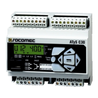
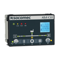
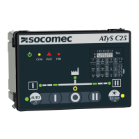
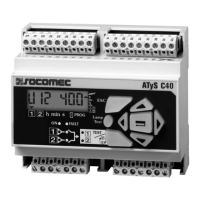
Product Name Communication
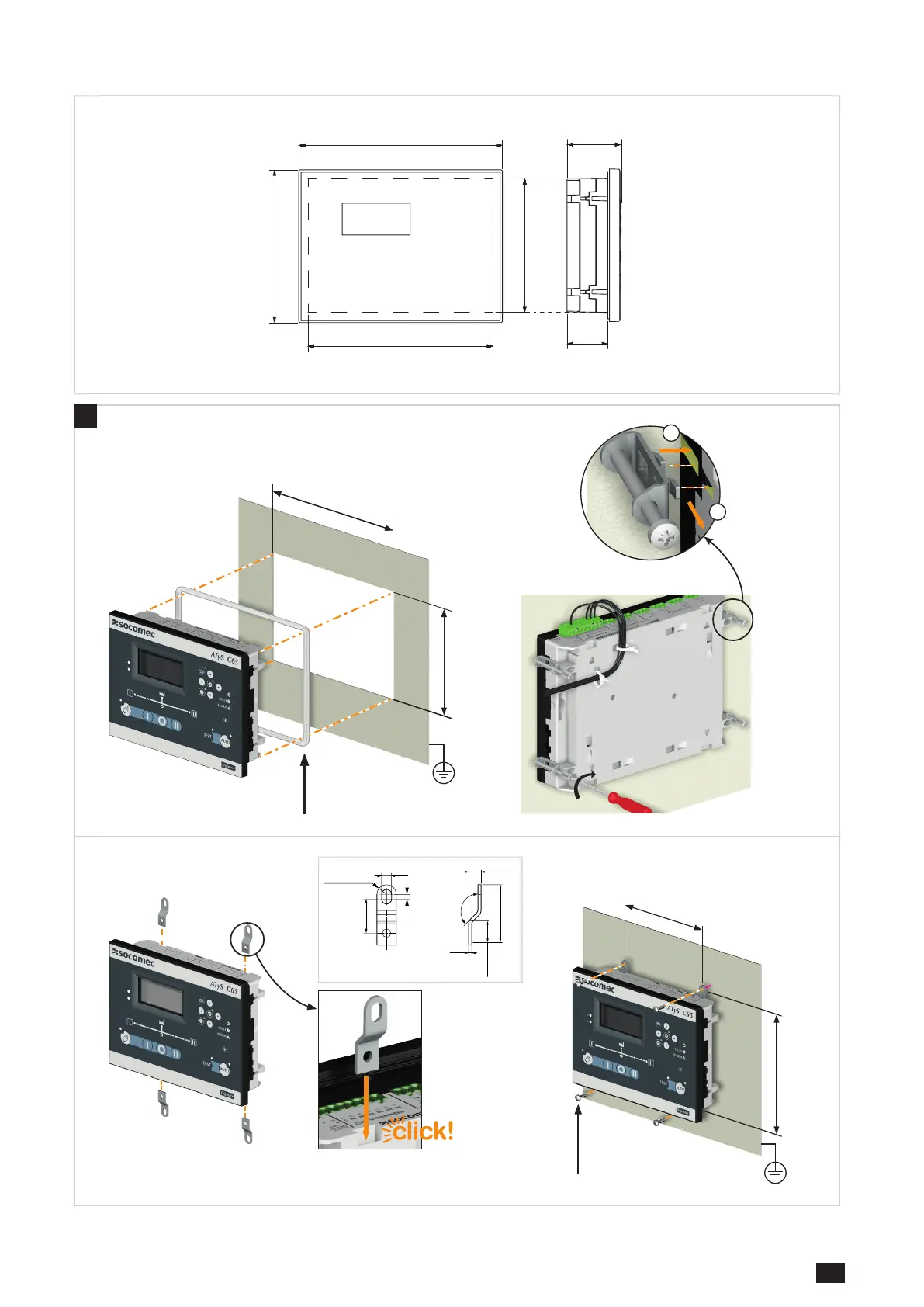
lock in place.
TYPE TERMINAL N° DESCRIPTION CHARACTERISTICS
RECOMENDED
CROSS SECTION
TIGHTENING
TORQUE
Sensing source 1
SOURCE 1
L1/L2/L3/N
Voltage sensing inputs source 1
& voltage supply (L1-L2)
Sensing voltage
50 - 575 V.a.c P-P - 50/60 Hz (+/- 10%)
Supply voltage (L1-L2)
88 - 576 V.a.c - 50/60Hz (+/- 10%) Ui 600V
0.75-2.5mm²
AWG 18-14
0.5-0.6 Nm
4.4-5.3 lb.in
Sensing source 2
SOURCE 2
L1/L2/L3/N
Voltage sensing inputs source 2
& voltage supply (L1-L2)
Inputs
71 IN1: programmable input 1
Do not connect to any external power
supply
0.5-2.5mm²
AWG 20-14
72 IN2: programmable input 2
73 IN3: programmable input 3
74 IN4: programmable input 4
75 IN5: programmable input 5
76 IN6: programmable input 6
70 Common point for inputs
Aux power supply 81/82
- : negative terminal for aux supply
+: positive terminal of aux supply
12-24 Vd.c.
Outputs
12/14/11 OUT1: programmable output 1
Dry contacts
8A / 277 VAC 50/60 Hz
5A / 24 VDC
1.5-2.5mm²
AWG 16-14
22/24/21 OUT2: programmable output 2
32/34/31 OUT3: programmable output 3
42/44/41 OUT4: programmable output 4
52/54/51 OUT5: programmable output 5 (latching)
62/64/61 OUT6: programmable output 6 (latching)
Current transformers IN/I3/I2/I1 CT neutal / CT phase C / CT phase B/ CT phase A CT input 1A or 5A
Serial connection RS485
Connection RS485
-: negative terminal of RS485 bus
+: positive terminal of RS485 bus
NC : Ground
RS485 bus insulated
LiYCY shielded twisted pair
0.14 to 1.5 mm²
30-14 AWG
0.22 -0.25 Nm
Digiware* DIGIBUS
Connection point for I/O 10 optional accessories &
digiware connection (must use 24 VDC input)
RJ 45 digiware cable - -
* For more information check I/O module instruction sheet ref 545597
 Loading...