Installing the Power Optimizers
SolarEdge Installation Guide – MAN-01-00002-1.6
22
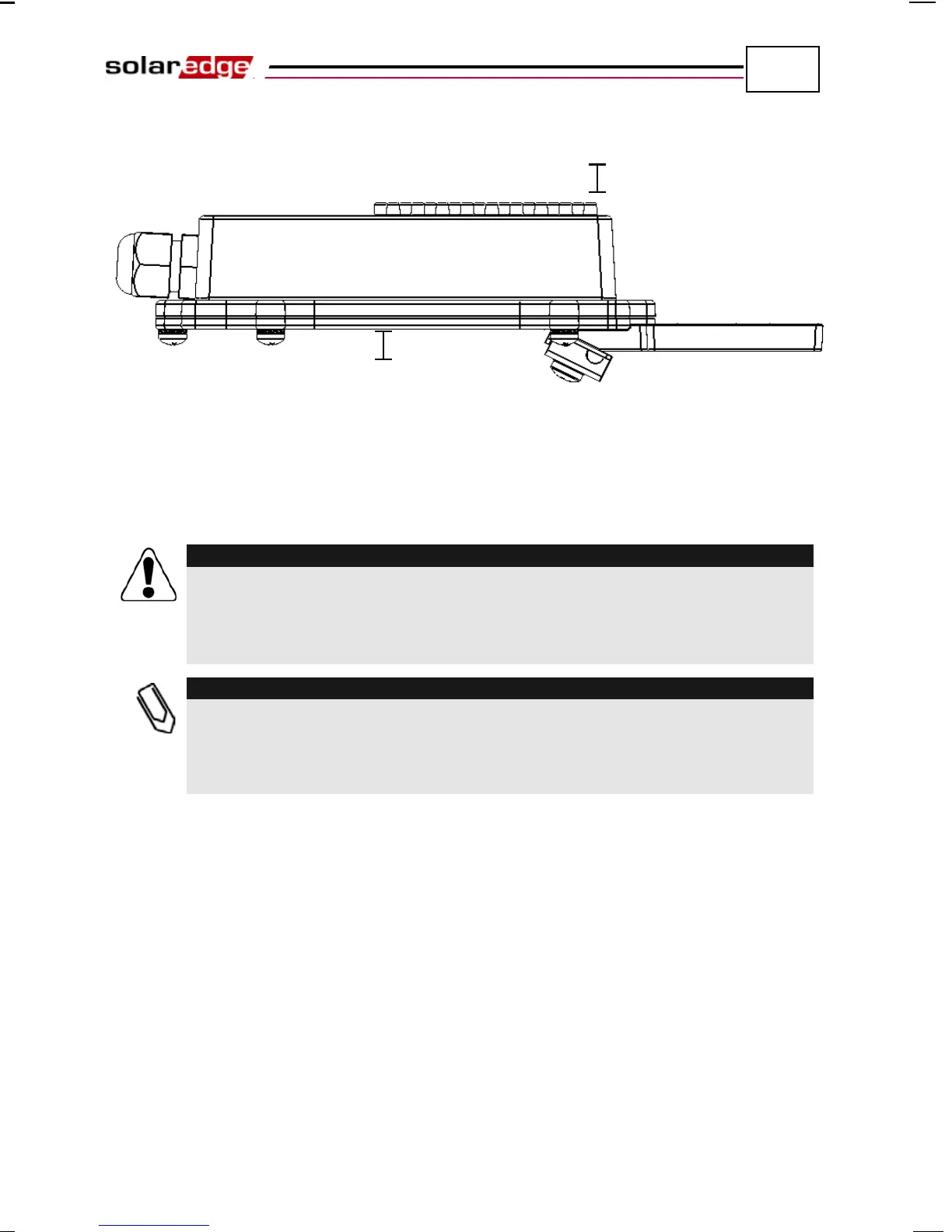
The following shows the required clearance on the top of the power optimizer.
Figure 6: Clearance – Side View
Connecting Power Optimizers
► To connect these power optimizers to the PV modules:
Verify that you have identified the inputs and outputs correctly. Do not connect PV
modules to power
optimizer outputs.
Vérifiez que vous avez identifié les entrées et sorties correctement. Ne pas
connecter des modules PV aux sorties des optimiseurs de puissance.
The power optimizer has reverse polarity protection. Even so, you must still verify
the correct polarity by checking the PV module’s polarity with a voltmeter. Some
module manufacturers may use connector polarity that is different from that used
by SolarEdge power optimizer inputs.
The input connectors are shown in the figures above. The output connectors
are in the middle of each side.