Installing the Inverter
SolarEdge Installation Guide – MAN-01-00002-1.6
35
Inverters that are maked in the diagram above with two asterisks (**) and that have
their
Neutral line connected can be set with the Auto Detect Grid option. In this
case, there is no requirement to configure them to a specific grid voltage.
Inverters that are connected to corner grounded grids
must have the L2 terminal
d conductor. For all other grids, L1 and L2 are
When connecting multiple single phase inverters in an installation connected to a
three
-phase grid, phase balancing may be required by the utility or grid operator.
supported in the SolarEdge inverters. Please refer to the
SolarEdge Phase Balancing Manual for more details.
Connecting the Single Phase Inverter
Connectors and Cables
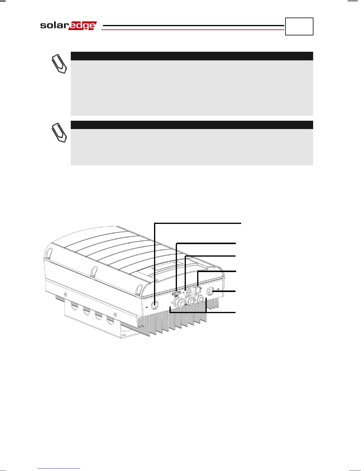
The following shows the Single Phase Inverter connectors:
Figure 12: Single Phase Inverter Connectors