Installing the Inverter
SolarEdge Installation Guide – MAN-01-00002-1.6
49
Connecting the AC
Use any of the AC side conduit inputs. Each punch-out opening has two sizes: ¾”
and 1”.
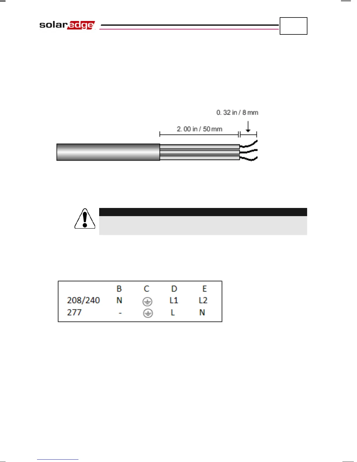
1 Strip off the isolation and expose the three wires in the AC cable, as follows:
The lengths of the wires to strip are as follows:
Figure 27: Wire Lengths to Strip – AC
• Strip 8 mm (1/3'') for contact.
• Individual cable length 50 mm (2'').
Make sure to connect the equipment grounding first.
Veillez à relier le conducteur de PE (la terre) d'abord.
2 Connect the wires to the appropriate terminal connectors. On the AC/DC
Switch chassis there is a label, shown in Figure 28, which illustrates how to
connect the wires when connecting to a 208V/240V grid or 277V grid. Be
sure to follow these connection instructions to ensure proper connection.
Figure 28: AC/DC Safety Switch AC Terminal Block Label
3 For the DCD-1ph-US-A switch, tighten the screws of each wire terminal
according to the following torque. The tightening moment is 1.2-1.5 Nm
(0.88-1.1 pound-foot). The DCD-1ph-US-B switch has no tightening screws.
For the DCD-1ph-US-B switch, push the wire in from the bottom with a
flathead screwdriver.
4 Verify that there are no stray strands outside each terminal connector and that
the unused ports of the terminals are tightened.