6-48
DCR-PC350/PC350E
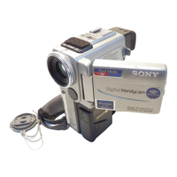
3-1-3. Adjusting Connectors
The measuring point of the playback RF signal is CN1015 of VC-
370 board. Connect the measuring instruments via the CPC-6
flexible jig (J-6082-370-C) and CPC-6 terminal board jig (J-6082-
371-A). Refer to “MECHANISM SECTION ADJUSTMENT” for
the measuring method. The following table lists the pin numbers
and signal names of CN1015.
Table 6-3-1.
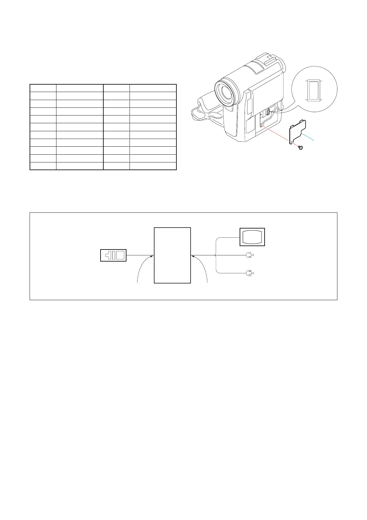
3-1-4. Connecting the Equipment
Connect the measuring instruments as shown in Fig. 6-3-2, and
perform the adjustments.
Pin No.
1
3
5
7
9
11
13
15
17
19
Signal Name
N.C.
N.C.
N.C.
MD2
XSYS RST
EEP SO
REC CRRT1
REG GND
SWP
REG GND
Pin No.
2
4
6
8
10
12
14
16
18
20
Signal Name
D 2.8V
N.C.
REG GND
XCS MC FLASH
EEP SI
EEP SCK
REC CRRT0
XCS EEP
FRRV
RF MON
Adjustment
remote
commander
(RM-95)
LANC jack
Main unit
AUDIO/VIDEO jack
TV monitor
VIDEO
(Yellow)
AUDIO L (White)
AUDIO R (Red)
Fig. 6-3-2.
Fig. 6-3-1.

 Loading...