— 18 —
DV MECHANICAL ADJUSTMENT MANUAL VII
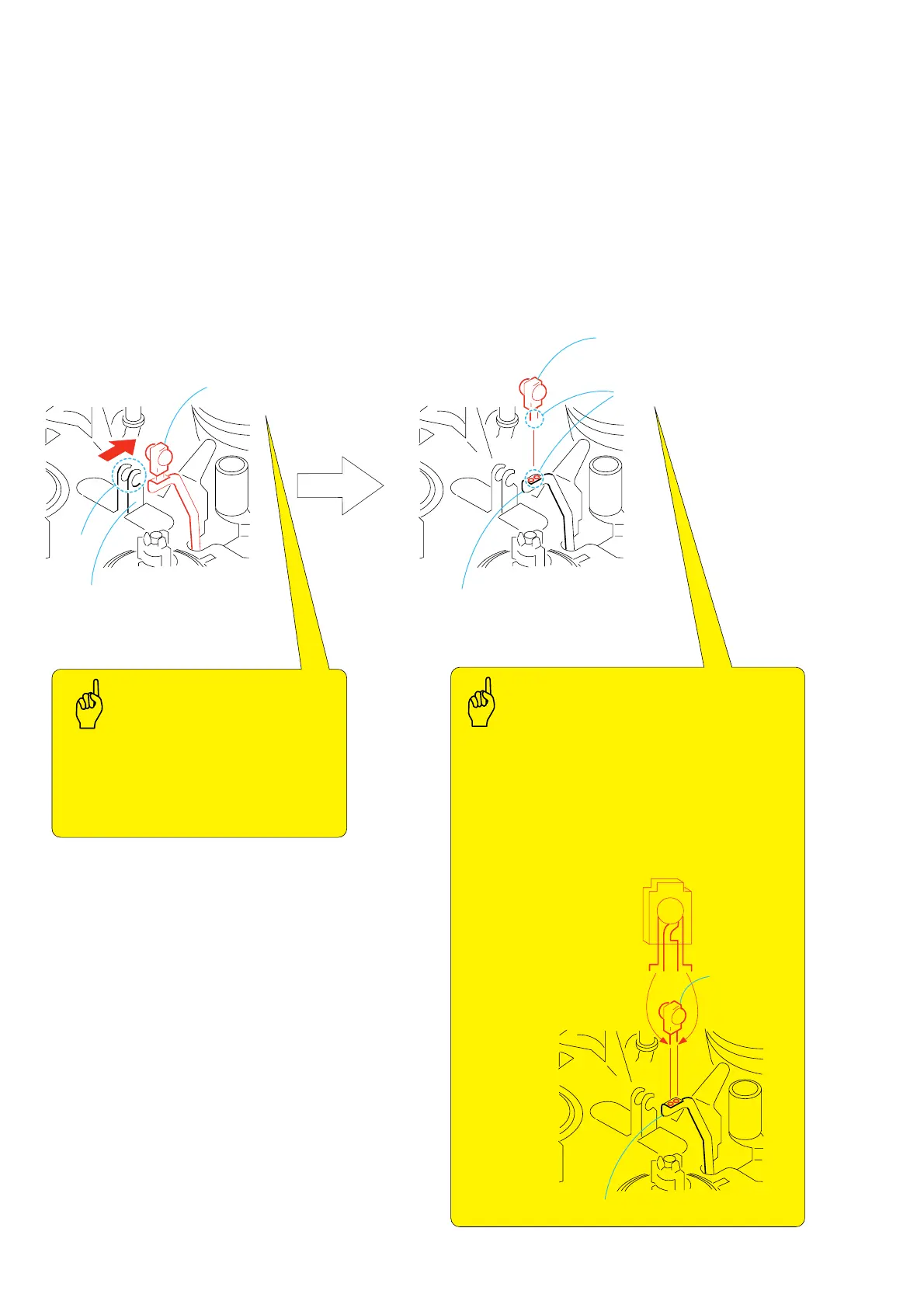
3-7. LED (D901)
1. Removal procedure
1) Remove LED (D901) and the FP-468 flexible board 1 from
the retainer plate.
2) Remove soldering at the two locations A and remove LED
(D901) 2.
2. Attachment procedure
1) Install the LED (D901) 2 to the FP-468 flexible board by
making soldering at the two locations A.
2) Fold the FP-468 flexible board 1 beneath the LED (D901)
with finger tip so that it is inserted into the B portion of the
retainer plate.
1
LED (D901),
FP-468 flexible board
LED (D901),
FP-468 FLEXIBLE BOARD
B
2
LED (D901)
LED (D901)
Soldering at the two locations
A
FP-468 flexible board
Direction of the terminal
is specified.
FP-468 flexible board
Rubber finger tip protection cover must be used.
Lead-free solder
Wire type: diameter
∅
0.6
Soldering iron: 941 made by Hakko
Soldering iron tip: T1-1BC
Temperature of the soldering iron tip: 300
±
10
°
C
Contacting time of soldering iron tip: within 2 sec.
Retainer plate
Points to be noted
• There must be no solder crack.
• There must be no scars and no
stains.
• The flexible board must have no
breakdown.
• The retainer plate and LED block
must have no deformation.
Points to be noted
Soldering



 To Next Page