— 32 —
DV MECHANICAL ADJUSTMENT MANUAL VII
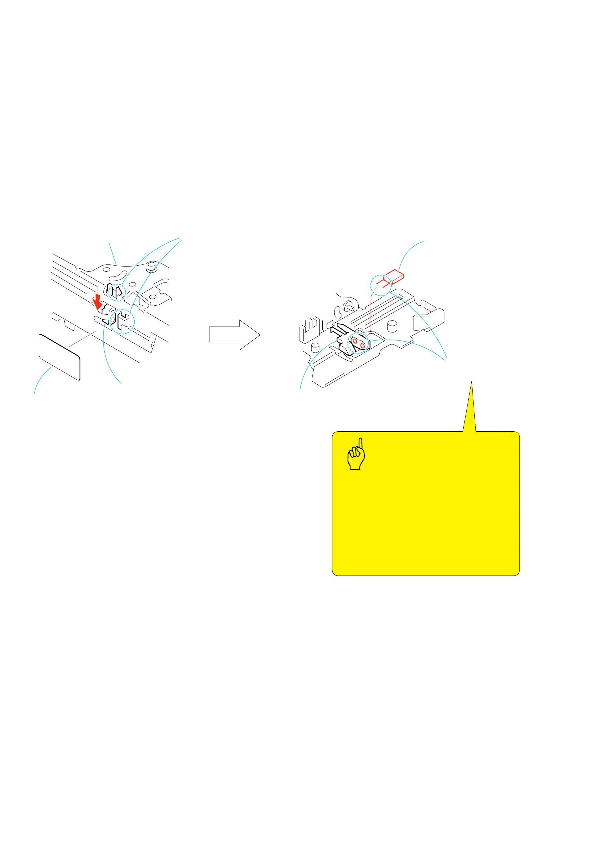
3-21.TOP Sensor (Q902)
1. Removal procedure
1) Peel off the MNO seal 1.
2) Release the two claws of the sensor holder (T) 2 at the two
locations A. Remove it from the LS chassis block assy by
sliding it in the direction of the arrow B.
3) Remove the soldering at the two locations B and remove the
TOP sensor (Q902) 3 and the sensor holder (T) 4.
2. Attachment procedure
1) Connect the TOP sensor (Q902) 3 and the sensor holder (T)
4 to the FP-468 flexible board by soldering them at the two
locations B.
2) Engage the two claws A to install the TOP sensor (Q902) 3
and the sensor holder (T) 4 in the LS chassis block assy.
3) Attach the MNO seal 1.
Two claws
A
1
MNO seal
2
Sensor holder (T)
LS chassis block assy
4
Sensor holder (T)
B
Soldering at the
two locations
B
3
TOP sensor (Q902)
Use the rubber finger tip cover
Lead-free solder
Wire type
Soldering iron
Soldering iron tip
Temperature of the
soldering iron tip
Contacting time of
soldering iron tip
:
∅
0.6
: 941 made by Hakko
: T1-1BC
: 300
±
10
°
C
: within 2 sec
Soldering
Points to be noted

 Loading...