— 27 —
DV MECHANICAL ADJUSTMENT MANUAL VII
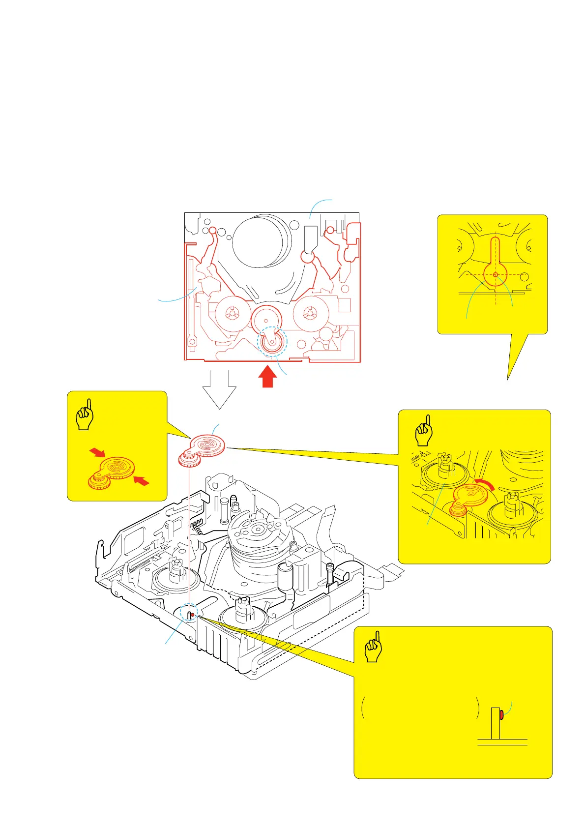
3-16.Gooseneck Gear Assy
1. Removal procedure
1) Move the LS chassis block assy 1 in the direction of the arrow
A to make it in YJ position.
YJ position: The position B where gooseneck gear assy can
be removed. (where the center of LS chassis hole matches with
junction gear shaft.)
2) Remove the gooseneck gear assy, holding it with C.
2. Attachment procedure
1) Apply grease to the gooseneck gear shaft D portion.
Amount of grease: a ball of grease of 1.0 mm diameter
Need no re-application to one which applied already.
2) Install the gooseneck gear assy, holding it with C in the
gooseneck gear shaft.
3) Move it closer to the S reel.
Apply grease
After installation, move it closer to
the S reel side.
• Do not apply grease to the
wrong position.
• Do not forget to apply grease.
• Do not make mistake about amount of grease.
• When applying grease, do not splash or touch
grease to any other parts and components.
Gooseneck gear shaft
Amount of grease: a ball of
grease of 1.0 mm diameter
2
Gooseneck gear assy
Hold the
C
portion
Shaft
D
B
The position where gooseneck gear assy can be removed.
(Where the center of LS chassis hole matches with junction gear shaft.)
junction gear shaft
LS chassis hole
1
LS chassis block
assy
S reel
A
Mechanism chassis block assy
C
C
Points to be noted
Apply Grease
YJ Position
GOOSENECK
GEAR ASSY
GOOSENECK GEAR ASSY
Points
to be noted
Key Points
in Re-assembling
Re-application of grease to
the point which is greased
already before is not necessary.