— 29 —
DV MECHANICAL ADJUSTMENT MANUAL VII
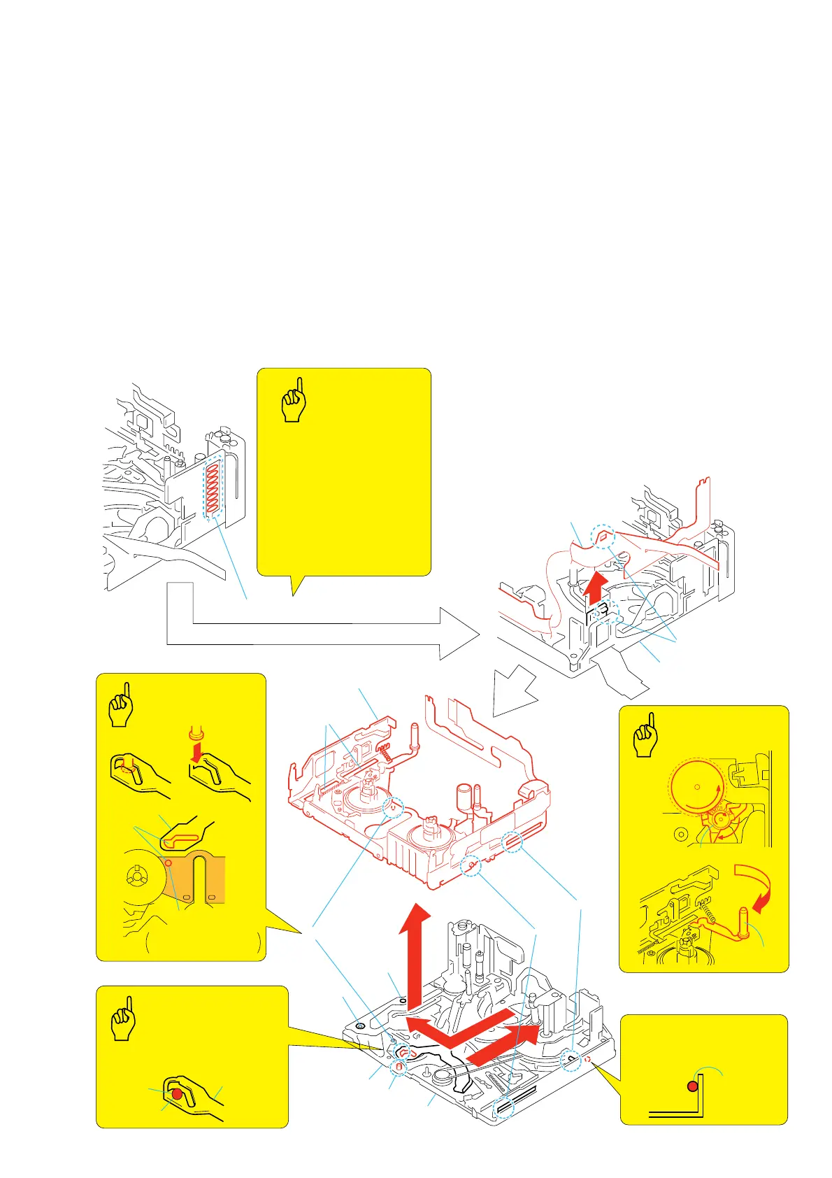
3-18.LS Chassis Block Assy and Mechanical Chassis Block Assy
2. Attachment procedure
1) Apply grease to the GL drive arm J portion and mechanism
chassis block L.
Amount of grease: a ball of grease of 1.0 mm diameter
2) Rotate the T reel table assy in the counter-clockwise direction
and move the brake T block to the position shown in Fig. 1.
(Fig. 1)
3) Move the TG2 arm block to the inner side. (Fig. 2)
4) Hold the cam groove of the GL driving arm with tweezers
through LS chassis hole K and pick it up.
5) Insert the GL drive shaft into the cam groove of the raised GL
drive arm using the trace mark of caulking on the side of the S
reel of the LS chassis block assy. (Fig. 3)
6) Align the pins E, F and G with the grooves.
7) Align the left side S1 screw hole and S2 shaft with the goove
H of the LS chassis block assy.
8) Move the LS chassis block assy in the direction of the arrow
I so that the YJ position is obtained.
YJ position: The position where gooseneck gear can be
installed. (Ref. 3-16)
9) Align the claw A and install the FL-468 flexible board 2 in
the mechanism chassis block assy.
10) Connect the soldering at the eight locations 1 and install the
FP-467 flexible board and the FP-468 flexible board 2.
1. Removal procedure
1) Remove soldering at the eight locations 1.
2) Release the claw A and remove the FP-468 flexible board 2
from the mechanical chassis block assy in the direction of the
arrow B.
3) Raise the front portion of the LS chassis block assy 3 so that
the pin C of the LS arm assy is removed. Move the LS chassis
block assy 3 in the direction of the arrow D and release the
three pins of E, F and G, and also groove.
4) Remove the LS chassis block 4 from the mechanical chassis
block assy.
A
C
J
D
G
G
E
I
F
B
2
FP-468
flexible board
Mechanical chassis
block assy
4
Mechanical chassis
block assy
3
LS chassis block assy
Groove
H
S2 shaft
S1 screw
hole
Brake (T) block assy
TG2 arm
block assy
LS arm assy
GL driving arm
Apply
grease
GL driving arm
Align
Guideline
Trace mark of GL
driving shaft caulking
(Fig. 3)
(Fig. 1)
(Fig. 2)
Lead-free solder
Wire type:
∅
0.6
Temperature of
the soldering iron tip: 350
°
C
Contacting time of
soldering iron tip: within 2 sec.
• Be careful not to create the
hollow soldering, Br, and
there must be no lacking
of parts.
• Be careful not to crash the
grip jog to the TG1 guide.
Key Points in
Re-assembling
Key Points in
Re-assembling
Apply Grease
Amount of grease:
a ball of grease of 1.0 mm diameter
Points
to be noted
Points
to be noted
1
Soldering at the eight locations.
Soldering
Apply grease when installing it.
Amount of grease:
a ball of grease of 1.0 mm
diameter
Apply Grease
Apply grease
(Inner side)