— 45 —
DV MECHANICAL ADJUSTMENT MANUAL VII
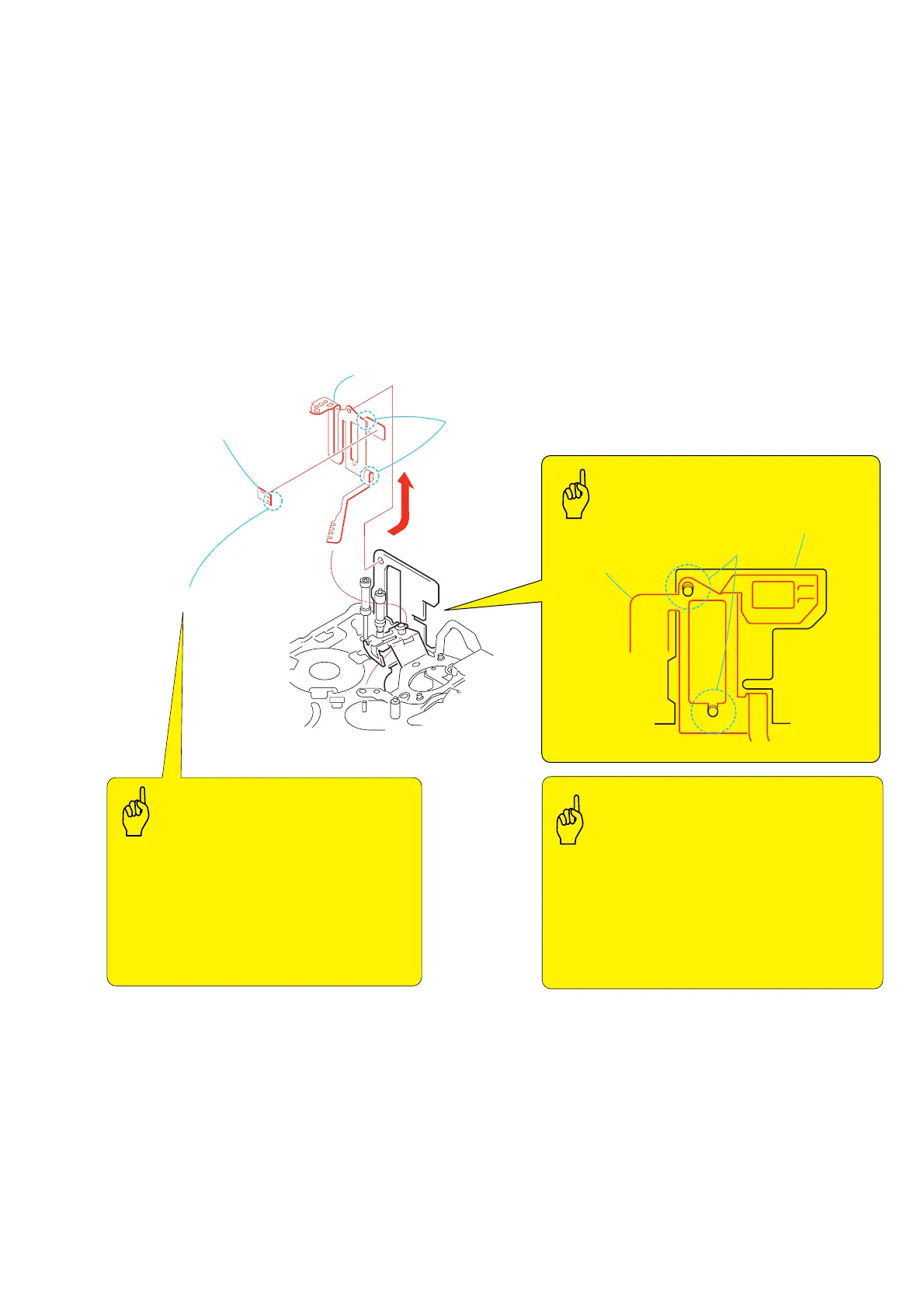
1. Removal procedure
1) Remove the soldering at the two locations 1 and remove the
FP-228 flexible board (DEW SENSOR) 2.
2) Remove the FP-467 flexible board 3 from the mechanical
chassis in the direction of the arrow.
2. Attachment procedure
1) Match the phase of the two holes A of the FP-467 flexible
board 3 with the holes of the mechanical chassis, and attach
them each other.
2) Attach the FP-228 flexible board (DEW SENSOR) 2 to the
FP-467 flexible board 3.
3) Connect the terminals at the two locations 1 by soldering.
3-34.FP-228 Flexible Board (DEW SENSOR) and FP-467 Flexible Board
1
Remove the soldering
at the two locations
3
FP-467 flexible board
FP-467
flexible board
Mechanical chassis
Two holes
A
2
FP-228 flexible board
(DEW SENSOR)
Lead-free solder
FP-467 FLEXIBLE BOARD
Bending the flexible board
at the two locations
Temperature of the soldering iron tip: 350
°
C
Contacting time of soldering iron tip: within 2 sec.
• Be careful not to create the hollow soldering, Br,
and there must be no lacking of parts. There must
not be solder ball.
• Be careful not to contact the soldering iron tip too
long time.
• Be careful not to break the flexible board to have
open circuit when installing and removing it.
• Be careful that flexible board must not override
on anything.
• Be careful that the two bending portions of the
FP-467 flexible board must not be bent excessively
that results in open circuit and breakdown of
flexible board.
• Do not rub the DEW sensor with any rubbing bars.
Key Points in Re-assembling
Points to be notedPoints to be noted
Soldering