6-55
DCR-PC350/PC350E
3-4. VIDEO SYSTEM ADJUSTMENTS
Note1: Before perform the video system adjustments, check that the
specified value of “54MHz/67.5 MHz Origin Oscillation
Adjustment” of “CAMERA SYSTEM ADJUSTMENT” is
satisfied.
And check that the data of page: 0, address: 10 is “00”. If not, set
data: 00 to this address.
Note2: NTSC model : DCR-PC350
PAL model : DCR-PC350E
Note3: The lens block (CD-537 board) must be connected when
performing the adjustments.
1. S VIDEO OUT Y Level Adjustment (VC-370 Board)
Mode CAMERA–TAPE
Subject Arbitrary
Measurement Point Y signal terminal of S VIDEO jack
(75Ω terminated)
Measuring Instrument Oscilloscope
Adjustment Page C
Adjustment Address 25
Specified Value A = 1000 ± 14mV
Note: The data of page: 0, address: 10 must be “00”.
Switch setting:
DEMO MODE (PICT. APPLI menu)......................................OFF
Adjusting method:
Order Page
Address
Data Procedure
1 0 01 01 Set the data.
2 8 4C 94 Set the data, and press PAUSE
button.
3 3 0C 02 Set the data, and press PAUSE
button.
4 C 25 Change the data and set the Y
signal level (A) to the specified
value.
5 C 25 Press PAUSE button.
6 3 0C 00 Set the data, and press PAUSE
button.
7 8 4C 96 Set the data, and press PAUSE
button.
8 0 01 00 Set the data.
2.
S VIDEO OUT Chroma Level Adjustment (VC-370 Board)
Mode CAMERA-TAPE
Subject Arbitrary
Measurement Point Chroma signal terminal of S VIDEO
jack (75Ω terminated)
External trigger: Y signal terminal of
S VIDEO jack
Measuring Instrument Oscilloscope
Adjustment Page C
Adjustment Address 26, 27
Specified Value Cr level : A = 714 ± 14mV (NTSC)
A = 700 ± 14mV (PAL)
Cb level : B = 714 ± 14mV (NTSC)
B = 700 ± 14mV (PAL)
Burst level : C = 286 ± 6mV (NTSC)
C = 300 ± 6mV (PAL)
Note: The data of page: 0, address: 10 must be “00”.
Switch setting:
DEMO MODE (PICT. APPLI menu) ......................................OFF
Adjusting method:
Order Page
Address
Data Procedure
1 0 01 01 Set the data.
2 8 4C 94 Set the data, and press PAUSE
button.
3 3 0C 02 Set the data, and press PAUSE
button.
4C26
Change the data and set the Cr signal
level (A) to the specified value.
5 C 26 Press PAUSE button.
6C27
Change the data and set the Cb signal
level (B) to the specified value.
7 C 27 Press PAUSE button.
8 Check that the burst signal level
(C) is satisfied the specified value.
9 3 0C 00 Set the data, and press PAUSE
button.
10 8 4C 96 Set the data, and press PAUSE
button.
11 0 01 00 Set the data.
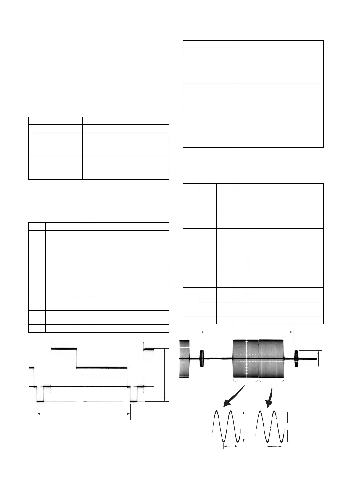
Fig. 6-3-5.
Fig. 6-3-6.
H
H
A
0.28 µsec (NTSC)
0.23 µsec (PAL)
B
0.28 µsec (NTSC)
0.23 µsec (PAL)

 Loading...