— 36 —
DV MECHANICAL ADJUSTMENT MANUAL VII
3-25.Coaster (S) Block Assy and Coaster (T) Block Assy
2. Attachment procedure
1) Install the coaster (S) assy 3 into the key hole of the GL (S)
assy 4 by rotating it.
2) Insert the coaster (S) block assy 2 into the coaster (S) block
shaft. While aligning it with the left groove of the drum base,
push it in the way that the V-groove comes to the top until it
reaches the pressure-bearing S.
3) Push in the coaster (T) block assy 1 along with the right groove
of the drum base. Align the phase of the GL gear S, GL gear
T and the GL drive arm at the three phasing locations. Then
install the coaster (T) block assy 1 in the coaster (T) block
assy shaft.
Coaster (S)
shaft
2
Coaster (S) block assy
3
Coaster (S) assy
1
Coaster (T)
block assy
Drum base groove
GL driving arm
GL driving arm
GL driving arm
GL gear (T) shaft
GL gear (T)
GL gear (T)
▲
mark
GL gear (S)
GL gear (S)
V groove
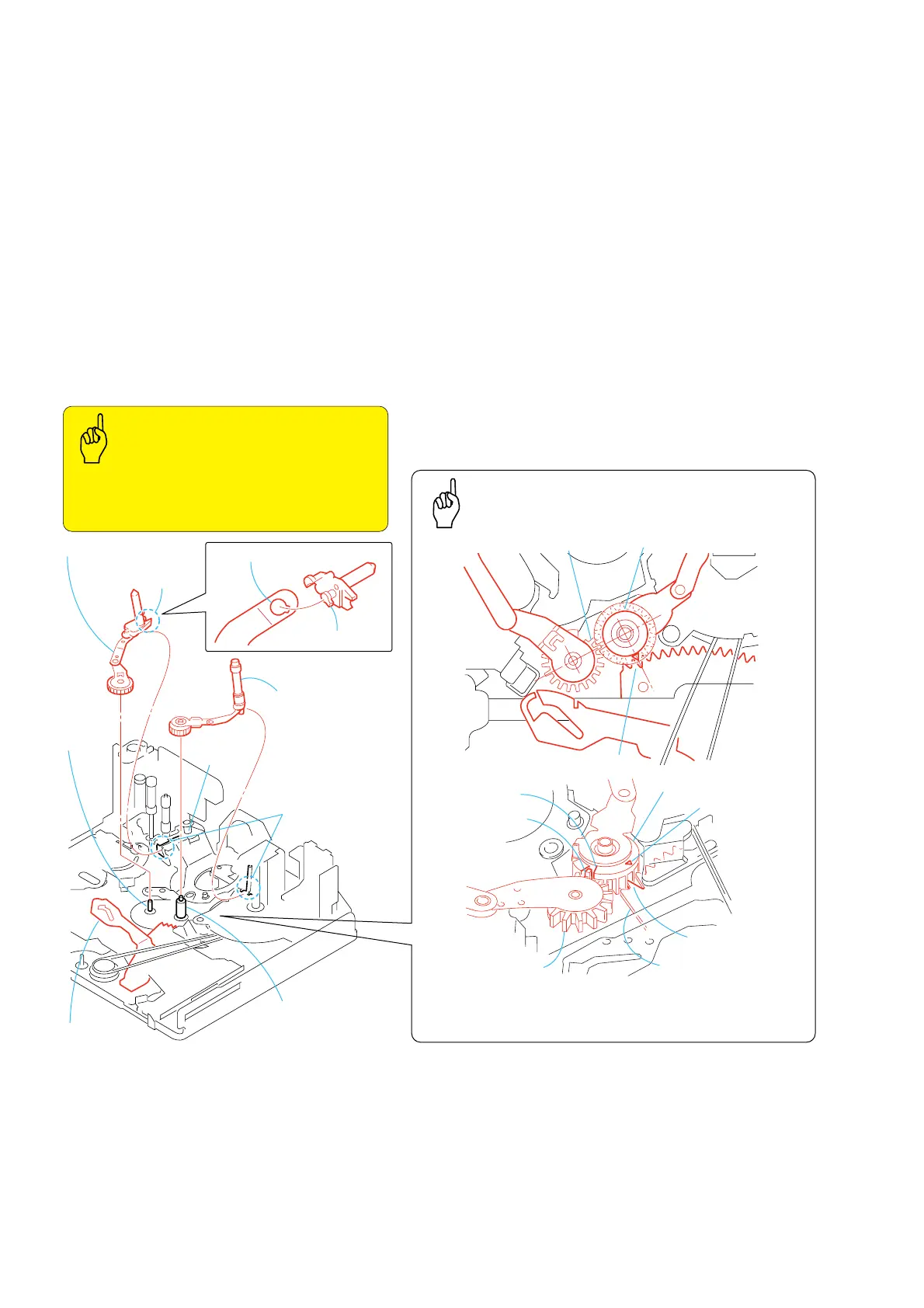
Phase Adjustment
When re-assembling, adjust the gear phase at the three
positions.
Key Points
in Re-assembling
Key Points in Re-assembling
• When aligning the coaster (S) assy with the left groove
of the drum base, the V-groove must come to the top.
• TG4 and TG5 must not have any stain and their arms
must not be deformed.
4
Keyhole of GL (S) assy
V-groove must
come to the top.
Pressure-
bearing S
The second tooth
from the left
• The second tooth from the left of the GL gear (S) and the V-groove
of the GL gear (T) must be in phase.
• The second tooth from the left of the GL drive arm and the
v
mark
must be in phase.
The second tooth
from the left
1. Removal procedure
1) Remove the coaster (T) block assy 1 from the coaster (T)
block shaft. Remove the coaster (T) block assy from the right
groove of the drum base.
2) Remove the coaster (S) block assy 2 from the coaster (S)
block shaft. Remove the coaster (S) block assy from the left
groove of the drum base.
3) Remove coaster (S) assy 3 by rotating it through the key hole
of GL (S) assy 4.