— 37 —
DV MECHANICAL ADJUSTMENT MANUAL VII
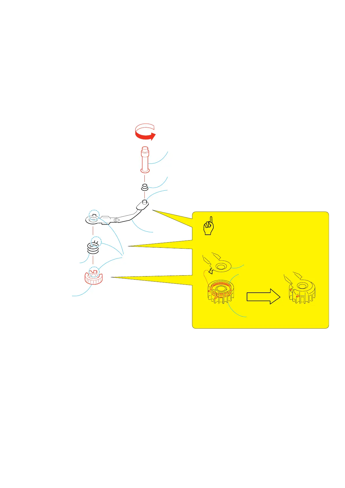
3-26.TG5 Roller Assy and GL Gear (T)
1. Removal procedure
1) Rotate the TG5 roller assy 1 in the direction of the arrow and
remove the TG5 roller assy 1 and the TG5 spring 2 from the
coaster (T) assy.
2) Release the claw (A) and remove the GL gear (T) 3 and the
torsion coil spring (GLT) 4 from the coaster (T) assy.
2. Attachment procedure
1) Install the GL gear (T) 3 and the torsion coil spring (GLT) 4
into the coaster (T) assy.
2) Install the TG5 spring 2 into the coaster (T) assy.
3) Install the TG5 roller assy 1 into the coaster (T) assy by rotating
it in the direction opposite to the arrow.
1
TG5 roller assy
2
TG5 spring
A
Claw
Coaster (T) assy
Coaster (T) shaft
Coaster (T) assy
3
GL gear (T)
GL gear (T)
(Fig. 1)
4
Torsion
spring (GLT)
Torsion spring (GLT)
Key Points in Re-assembling
COASTER (T) ASSY, GL GEAR (T),
TORSION SPRING (GLT)