— 13 —
DV MECHANICAL ADJUSTMENT MANUAL VII
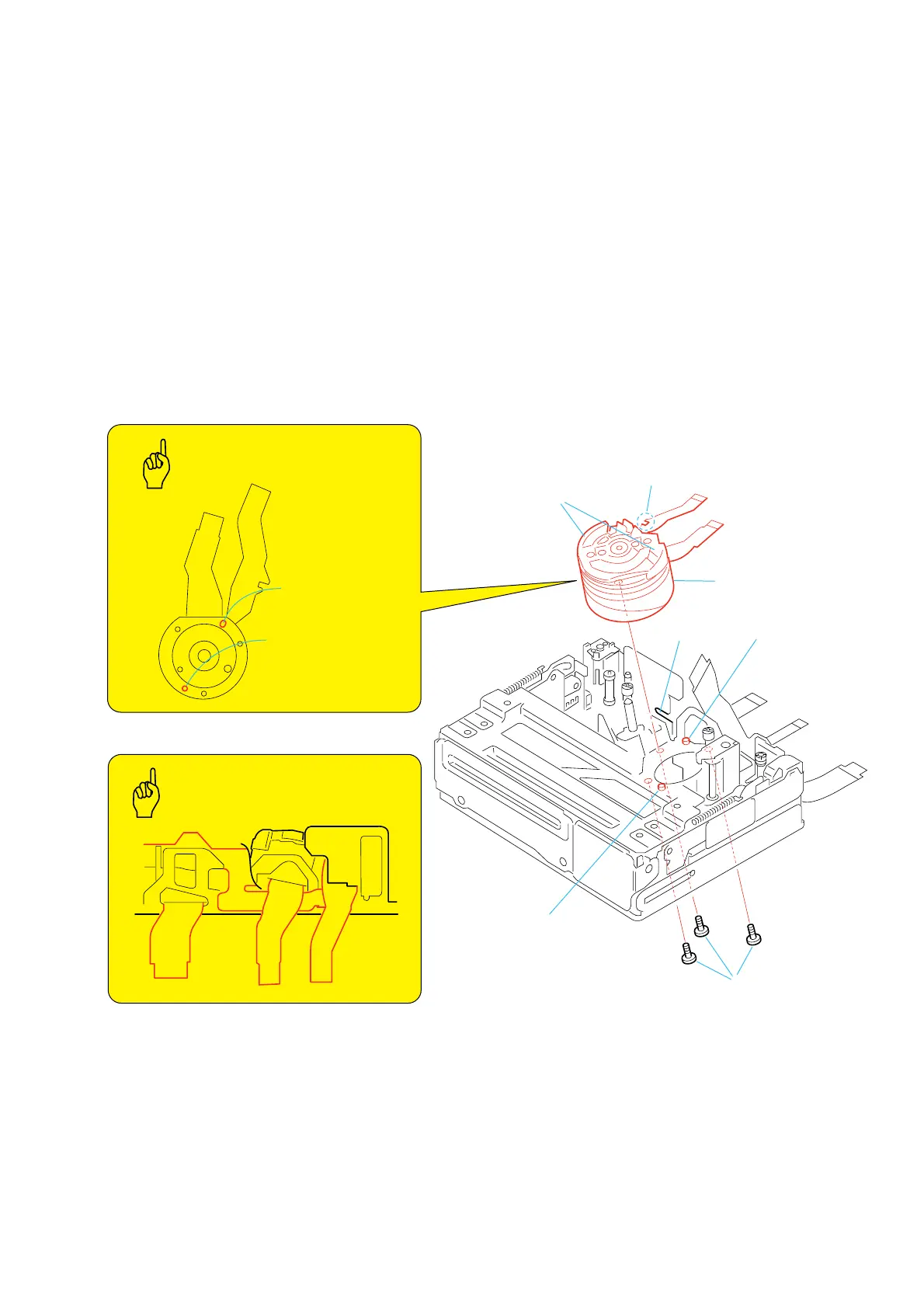
3-2. Drum
1. Removal procedure
1) Remove head drum flexible board C from the notch of the
mechanical chassis block assy.
2) Remove the drum fixing screw (M1.4 × 1.3) 1 and remove
the drum assy 2.
2. Attachment procedure
1) Ensure that head drum fixible board is hooked on the tape
supporter block.
2) Hold the tape-supporter block of the drum 2 and insert the
drum flexible board into the mechanical chassis block assy.
3) Insert the two reference holes A and B of the drum into the
reference pins A and B of the drum base assy.
4) Hook the flexible board C portion on the notch.
5) Install the three drum fixing screws (M1.4 × 1.3) 1 in the
order starting from D, then E, and finally F. Then tighten
the screws.
Tightening torque: 0.059 ± 0.01N•m (0.6 ± 0.1kgf•cm)
Return E 120°, then apply the screw locking paint (Neji lock).
6) Clean the drum by referring to section2-1.
7) Perform the tape path adjustment. (Refer to “4-4. Tape Path
Adjustment”.)
Long hole
(reference A)
Hole
(reference B)
1
Three Drum
fixing screws
D
E
C
F
2
Drum
Tape supporter block
Reference pin A
Notch
Reference pin B
Drum (rear view)
Key Points
in Re-assembling
Key Points
in Re-assembling
Drum Flexible Board Processing