— 28 —
DV MECHANICAL ADJUSTMENT MANUAL VII
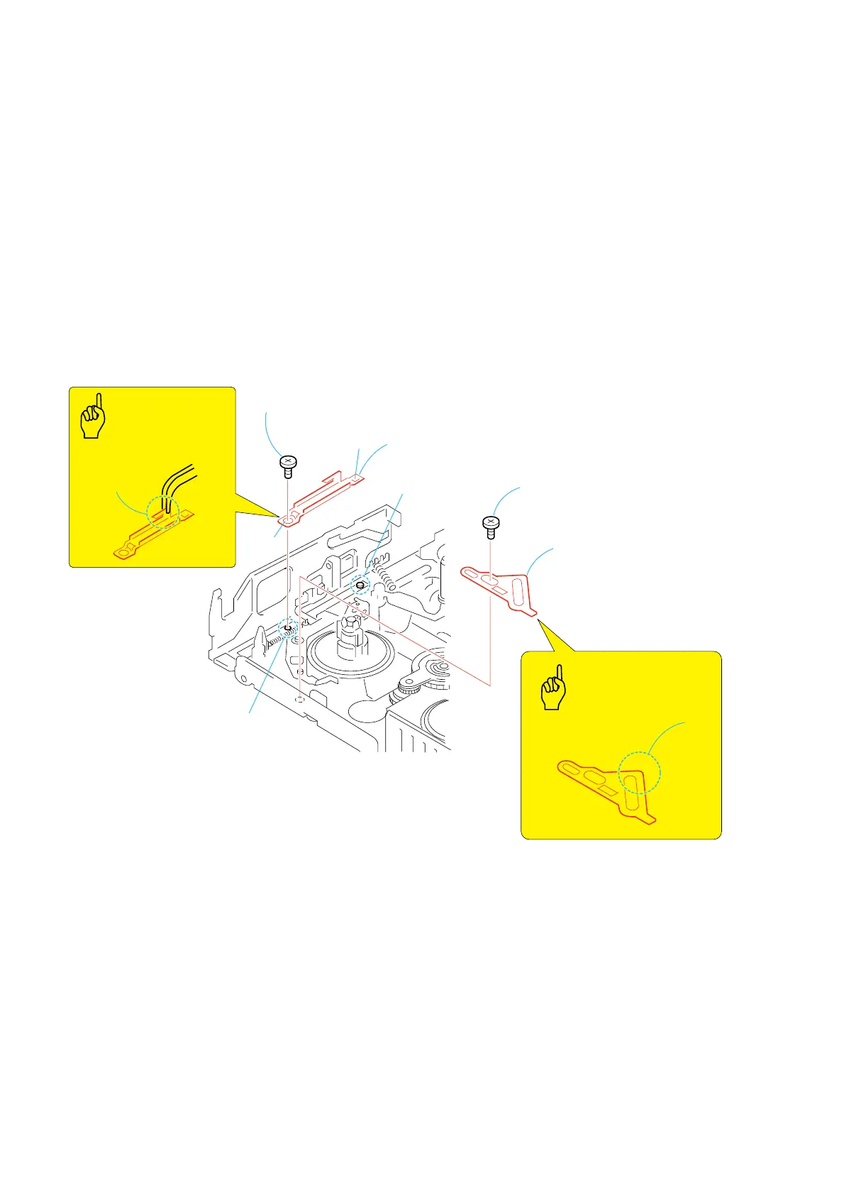
3-17.LS Guide Retainer and LS Cam Plate
1. Removal procedure
1) Remove the screw (special head screw M1.4 × 2.0) 1. and
remove the LS guide retainer 2.
2) Remove the screw (special head screw M1.4 × 1.4) 3 and
remove the LS cam plate 4.
2. Attachment procedure
1) Hold the LS cam plate with A and place it aligning the two
dowels. Tighten the screw (special head screw M1.4 × 1.4) 3
in half way.
2) Adjust the LS cam plate by referring to section 4-5.
3) Hold the LS guide retainer 2 with B and hook its key hole
C on the S2 shaft, and align the hole D to S1 screw hole.
4) Install the screw (special head screw M1.4 × 2.0) 1 in the S1
screw hole.
Tightening torque: 0.059 ± 0.01N•m (0.6 ± 0.1kgf•cm)
2
LS guide retainer
C
D
1
Screw
(M1.4
×
2.0)
3
Screw
(M1.4
×
1.4)
4
LS cam plate
S2 shaft
S1 screw hole
B
A
LS GUIDE RETAINER
Points
to be noted
LS CAM PLATE
Points
to be noted
Hold the
B
portion
Hold the
A
portion