— 49 —
DV MECHANICAL ADJUSTMENT MANUAL VII
4-4. Tape Path Adjustment
4-1. Adjustment Preparation
1) Clean the tape running surface (tape guides, drum, capstan,
pinch roller) referring to section 2-2.
2) Connect the adjustment remote commander (Ref. No. J-13) to
the LANC terminal of the machine. Set the HOLD switch to
ON.
3) Connect an oscilloscope to CN1004 of the VC-312 board via
the CPC-7 jig (J-6082-382-A). (In the case of DCR-TRV22K)
Oscilloscope CH1: VC-312 board CN1004 pin2 (Note 1)
EXT. TRIG: VC-312 board CN1004 pin4
Note 1: Connect CN1004 pin2 and pin6 (GND) with a 75-ohm
resistor (1-247-804-11).
4) Play back the tracking alignment tape (XH 2-1) (Ref. No. J-5).
5) Select page: 0, address: 10 and set data: 00. (Note 2)
6) Select page: 3, address: 26 and set data: 31, and press the PAUSE
button. (Note 2)
7) Select page: 3, address: 33 and set data: 08. (Note 2)
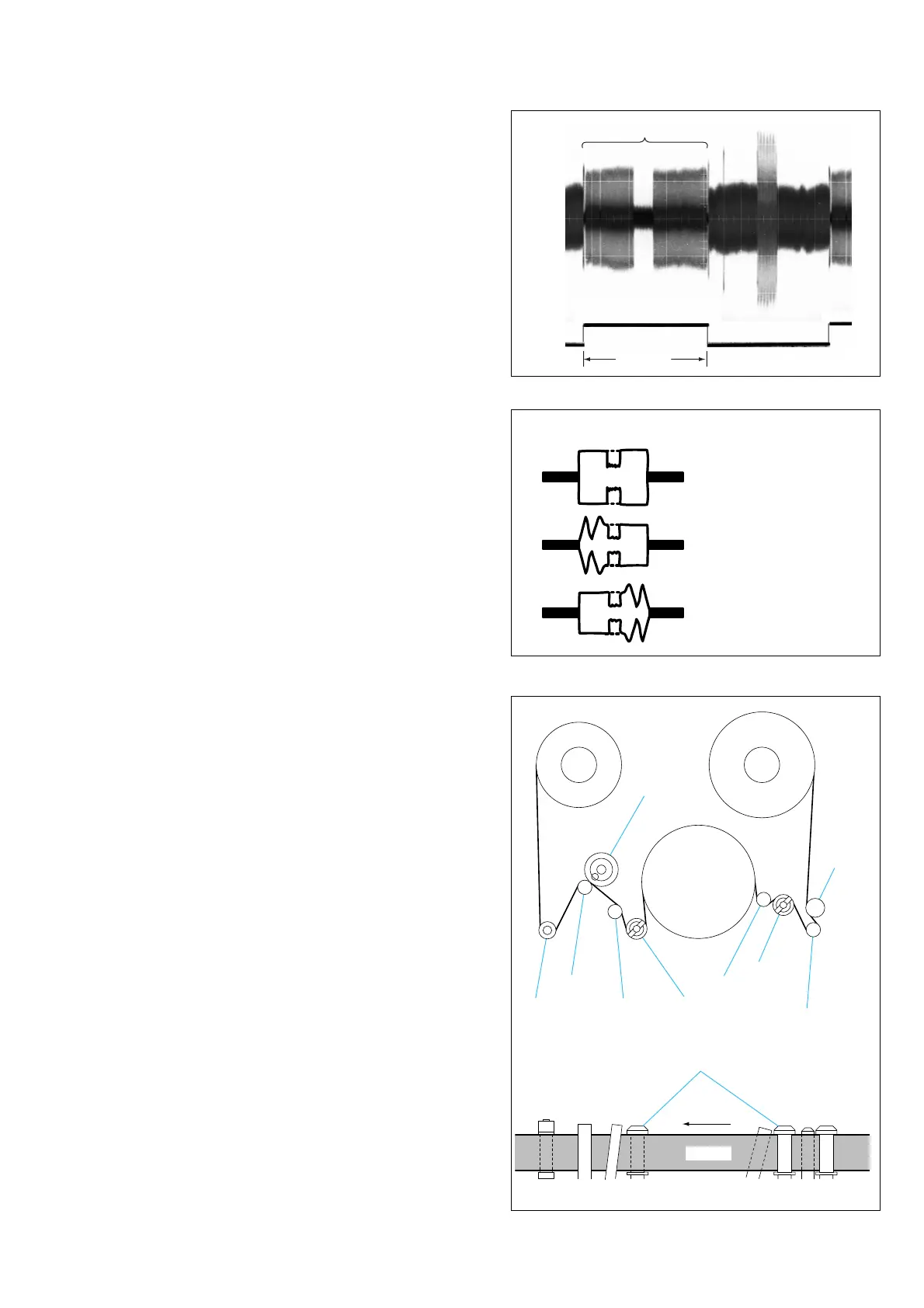
8) Confirm that the RF waveform on the scope is flat at both of
the entrance side and the exit side. (Refer to Fig. 4-4A.)
If the RF waveform is not flat either at the entrance side or the
exit side (refer to Fig. 4-4 B and C), perform the adjustment of
section 6-2 and later.
9) When the required conditions of step 8) are satisfied, perform
[Required Work upon Completion of Adjustment] as described
below upon completion of adjustment/check.
[Required Work upon Completion of Adjustment]
1) Connect the adjustment remote commander (Ref. No. J-13) to
the LANC terminal of the machine. Set the HOLD switch to
ON.
2) Select page: 0, address: 10 and set data: 00. (Note 2)
3) Select page: 3, address: 26 and set data: 00, and press the PAUSE
button. (Note 2)
4) Select page: 3, address: 33 and set data: 00. (Note 2)
Note 2:Page and address numbers differ depending on each model.
Please to Service Manual of the respective models. Page and
address numbers of DCR-TRV22K are shown in this manual.
CH1
CH2
(Trigger)
Envelope must be flat
3.3 msec
A
Normal
B
Entrance side is defective
C
Exit side is defective
Entrance side
Exit side
T reel table
Pinch roller
Capstan
Capstan
TG7 guide
FWD
TG3 guide
TG4 guide
TG2 guide
(tension regulator)
TG1 guide
TG1
TG3TG4TG5TG6TG7 TG2
Tape must run while maintaining contact with the
upper flange. There must not exist a large tape curl.
TG6 guide TG5 guide
S reel table
Drum
Tape
Fig. 4-3
Fig. 4-4
Fig. 4-5














 To Next Page