— 48 —
DV MECHANICAL ADJUSTMENT MANUAL VII
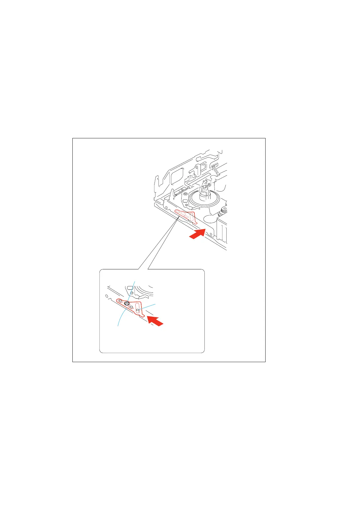
4-3. LS Cam Plate Position Adjustment
1. Adjustment Procedure
1) Loosen the LS cam plate fixing screw (special head screw
M1.4 × 1.4) by 180 degrees.
2) Set the STOP mode.
3) While pressing the center of the LS chassis block with the
force of 1.5 ± 0.5 N (150 gf ± 50 gf), move the LS cam plate
toward the S reel side with the force of 0.147 ± 0.01 N•m (2300
gf ± 200 gf) and tighten the LS cam plate fixing screw (special
head screw M1.4 × 1.4) 1.
Tightening torque: 0.098 ± 0.01 N•m (1.0 ± 0.1 kgf•cm)
LS cam plate fixing screw
Pin of the LS
arm assy
Move the LS cam
plate with the force
of 22
±
2 N
(2300 gf
±
200 gf)
Pressing the center of the LS
chassis block with the force of
1.5
±
0.5 N (150 gf
±
50 gf).
LS cam plate
Fig. 4-2







 To Next Page