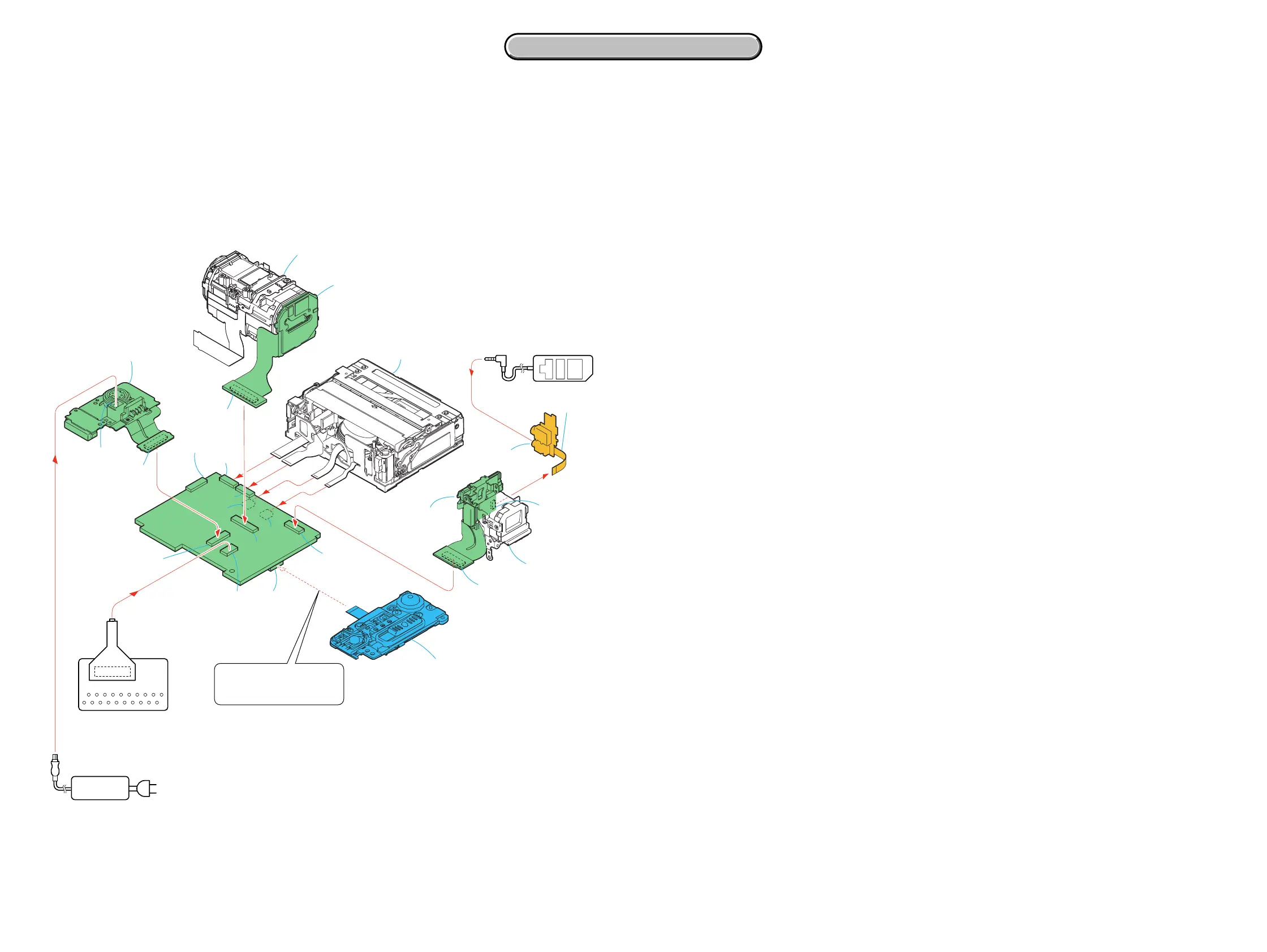
DCR-PC350/PC350E
VC-370
AC power
adaptor
AC IN
[SERVICE POSITION TO CHECK THE VTR SECTION]
Connection to Check the VTR Section
To check the VTR section, set the VTR to the "Forced VTR power ON" mode.
Operate the VTR functions using the adjustment remote commander (with the HOLD switch set in the OFF position.)
Setting the "Forced VTR Power ON" mode
1) Select page: 0, address: 01, and set data: 01.
2) Select page: 0, address: 10, and set data: 00.
3) Select page: A, address: 10, set data: 02, and press
the PAUSE button of the adjustment remote commander.
Control switch block (PS7450)(14P)
Exiting the "Forced VTR Power ON" mode
1) Select page: 0, address: 01, and set data: 01.
2) Select page: 0, address: 10, and set data: 00.
3) Select page: A, address: 10, set data: 00, and press the
PAUSE button of the adjustment remote commander.
4) Select page: 0, address: 01, and set data: 00.
Adjustment remote
commander (RM-95)
CR-048 board
Lens section
FP-995 Flexible
board (12P)
CN2503
CN8500
DC-IN jack
CN2502
CN2501
CN1002
CN1801
CN1004
CN2500
CN2503
CN1008
VC-370 board
Mechanism deck
LANC
LANC
jack
DC-IN
CN1501
20
19
2
1
CN1015
(CPC)
EVF section
SE-151 board
(To eject a cassette, connect
the control switch block.
(PS7450))
CN7301
CD-537 board
CPC-6 terminal board jig
(J-6082-371-A)
CPC-6 flexible jig
(J-6082-370-C)
2-7 2-8
2. DISASSEMBLY
2. DISASSEMBLY
 Loading...