1-3
DCR-PC350/PC350E
ENGLISH JAPANESE
ENGLISH JAPANESE
4. DISCHARGING OF THE FLASHLIGHT POWER SUPPLY CAPACITOR
The power supply capacitor (C1001) of the flash unit (FL7450) is charged up to the maximum 300V potential.
There is a danger of electric shock by this high voltage when the capacitor is handled by hand. The electric shock is caused by the charged
voltage which is kept without discharging when the main power of the unit is simply turned off. Therefore, the remaining voltage must be
discharged as described below.
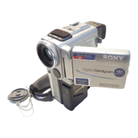
4-1. PREPARING THE SHORT JIG
To preparing the short jig. a small clip is attached to each end of a resistor of 1kΩ/1W (1-215-869-119)
Wrap insulating tape fully around the reads of the resistor to prevent electric shock.
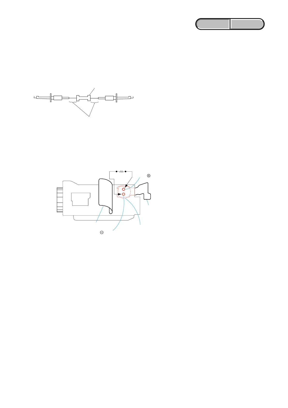
4-2. DISCHARGING THE CAPACITOR
1 Remove the rear cabinet assembly.
2 Remove the top cabinet assembly.
3 Open the insulation sheets.
4 Short-circuit between 3 and # terminal of the capacitor (C1001) with short jig about 10 seconds.
1 k
Ω
/1 W
Wrap insulating tape
Short jig (1k
Ω
/1W)
Insulation shee
C1001
Insulation sheet
Hole of
terminal
Hole of
terminal