117
English
4-4. I/O Connector
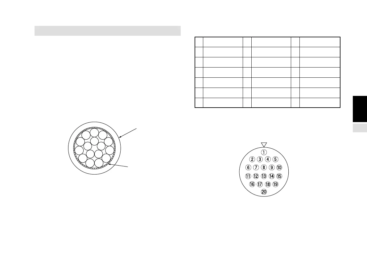
Interface cable
Use a shielded cable as shown in the figure below for the
interface cable to be connected to the I/O connector. Connect
the shielding to the shell of the I/O connector. Connect the
0 V separately from the shielded cable. (Please procure the
connector and shielded cable.)
Sectional diagram of interface cable
Input signal pin assignment
1 G2 8 +Vcc 15 EX. OUT2
2 EX. RESET 9 +5 V 16 CMP0 (Note)
3 NC 10 EX. OUT1 17 CMP1 (Note)
4 NC 11 EX. IN 18 CMP2 (Note)
5 NC 12 NC 19 CMP3 (Note)
6 EX. RCL 13 TTL1 20 0 V
7 NC 14 TTL2
Note: These pins are used when the optional comparetor
units LZ51-K or LZ51-R are inserted.
Connector pin arrangement (as seen on the rear panel)
Connector : Hirose Electric round multipolar connector
HR25-9TP-20P or equivalent product
Knitted shield
Outer cover