118
English
+5V
4.7µF/50V
G2
Vcc
+5V
1
0V
0V
0V
Vcc
G2
GND
1
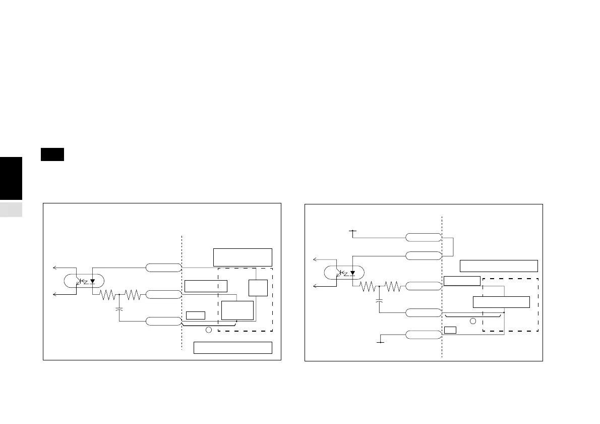
4-4-1. Overview of External Contact Point Input
Input circuit of external input signal
•
When you use the external input, connect the external input terminal to GND (common terminal) for at least 25 ms. When you
input the external input signal again, provide an OFF time of at least 30 ms.
•
We recommend that you use SN75451 or SN75452 as electronic switches.
•
Use a shielded connection cable and connect the shielding to the shell of the I/O connector. Connect the common cable
separately from the shielded cable. (Please procure the switch and shielded cable.)
Note When using this contact point input as an external zero point, you can only use contact point switches or other ON/OFF
signals. You cannot use Sony Precision Technology Magne-switches.
•
Input circuit
Switching
circuit
To internal
circuit
470 1 kΩ
Pin 8
4.7 µF/50V
+
Pin 1
Pin 2, 6, 11
Power
supply
Input signal
Pin 9
Pin 1
Pin 2, 6, 11
Pin 8
Pin 20
Input signal
<During +24 V, +12 V or other external power supply
operation>
(Note: +5 V operation is also possible.)
<During internal +5 V operation>
Input signal
Connect circuit example
Input signal
Switching circuit
→
Connect circuit example
→
Apply + 24V
(or + 12V)
470
1kΩ
+



 To Next Page