3. Remove the inside panel assembly. (Refer to “2-4-1. Inside Panel Assembly”.)
4. Remove the outside panel assembly. (Refer to “2-5-1. Outside Panel Assembly”.)
5. Remove the top panel assembly. (Refer to “2-6. Top Panel Assembly”.)
6. Remove the SxS slot assembly. (Refer to “2-7-1. SxS Slot Assembly”.)
7. Remove the front panel assembly. (Refer to “2-8-1. Front Panel Assembly”.)
8. Remove the rear panel assembly. (Refer to “2-9. Rear Panel Assembly”.)
9. Remove the IO-255 assembly. (Refer to “2-11. IO-255 Board”.)
10. Remove the main heat spreader DCP. (Refer to “2-12. DCP-56 Board”.)
11. Remove the handle assembly. (Refer to “2-13-1. Handle Assembly”.)
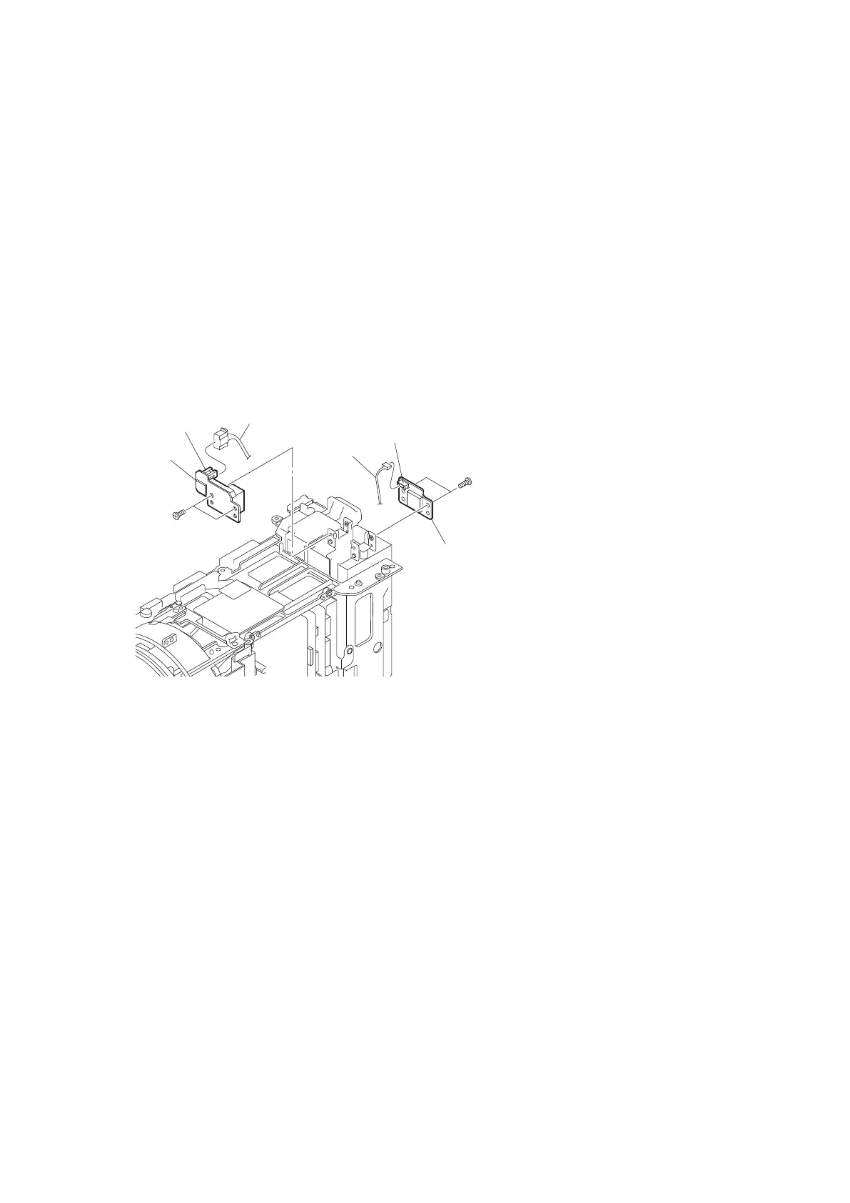
Procedure
1. Disconnect the harness from the connector CN100 on the DC-167 board.
2. Remove the two precision screws (M2 x 4) to detach the DC-167 board.
3. Disconnect the harness from the connector CN100 on the PSW-97 board.
4. Remove the two precision screws (M2 x 4) to detach the PSW-97 board.
Precision screws
(M2 x 4)
DC-167 board
PSW-97 board
CN100
CN100
Harness
Harness
Precision screws
(M2 x 4)
5. Install the removed parts by reversing steps of removal.
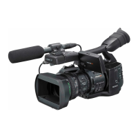
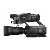
PMW-200/PMW-EX280
2-46