11. Remove the handle assembly. (Refer to “2-13-1. Handle Assembly”.)
12. Remove the front lens assembly. (Refer to “2-14-1. Front Lens Assembly”.)
Procedure
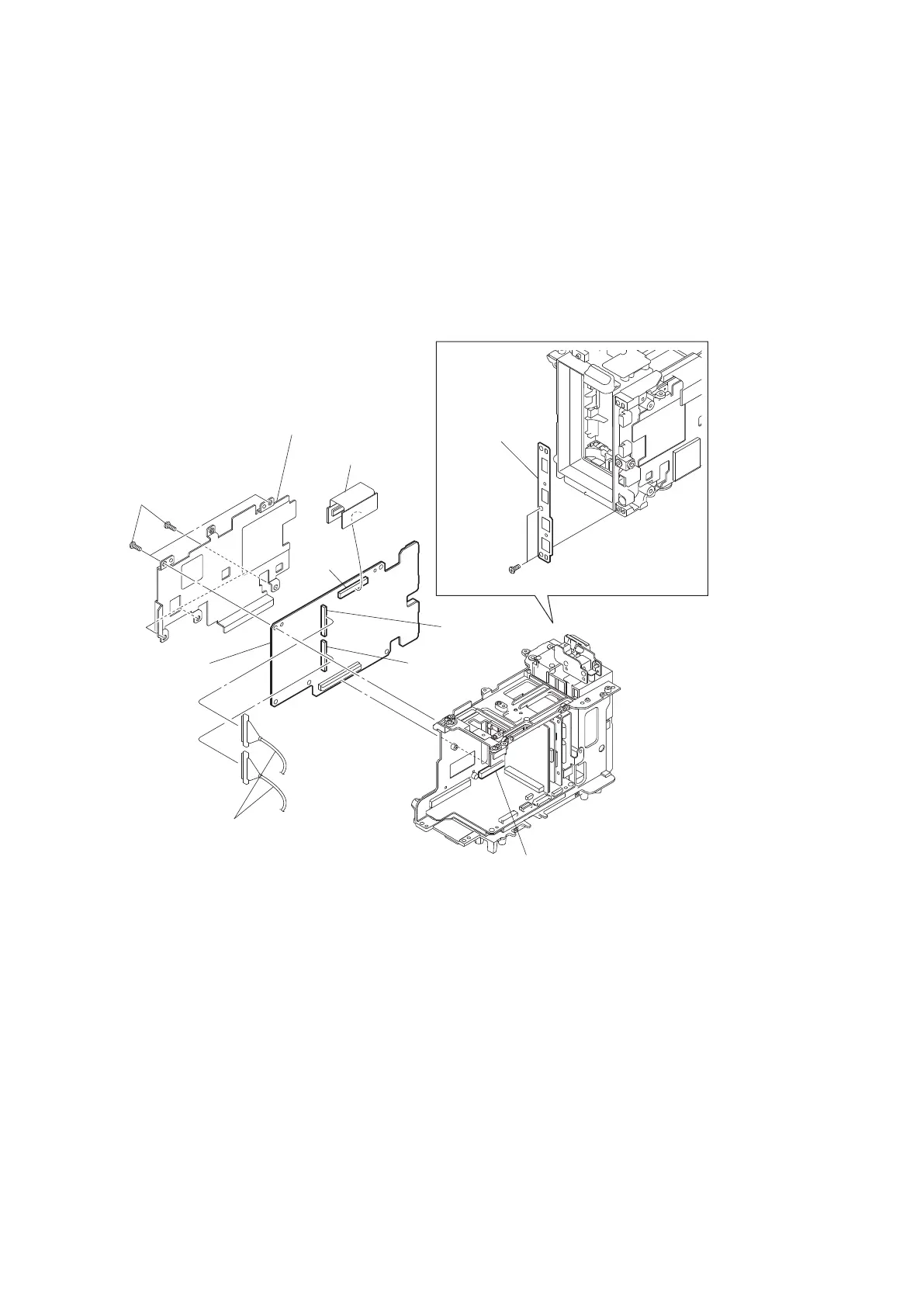
1. Remove the two precision screws (M2 x 4) to detach the USB bracket.
2. Remove the five precision screws (M2 x 4) to detach the main heat spreader DCP.
3. Remove the DPR-343 board from the connector CN200 from the AU-342 board.
4. Remove the HN-384 board from the connector CN2600 on the DPR-343 board.
5. Disconnect the two coaxial cables with connectors from the two connectors CN1400 and CN1401 on the DPR-343
board.
Precision
(M2 x 4)
Precision
(M2 x 4)
HN-384 board
Heat spreader DCP
DPR-343 board
CN1401
CN2600
CN1400
Coaxial cables with connector
USB bracket
CN200
(AU-342 board)
6. Install the removed parts by reversing steps of removal.
2-16-3. AU-342 Board, RE-298 Board, RE-299 Board, and RE-300 Board
Preparation
1. Remove the battery lid. (Refer to “2-2. Lithium Battery”.)
2. Remove the bottom cover. (Refer to “2-3. Bottom Cover and Tripod Washer”.)
3. Remove the inside panel assembly. (Refer to “2-4-1. Inside Panel Assembly”.)
4. Remove the outside panel assembly. (Refer to “2-5-1. Outside Panel Assembly”.)
5. Remove the top panel assembly. (Refer to “2-6. Top Panel Assembly”.)
6. Remove the SxS slot assembly. (Refer to “2-7-1. SxS Slot Assembly”.)
7. Remove the front panel assembly. (Refer to “2-8-1. Front Panel Assembly”.)
8. Remove the rear panel assembly. (Refer to “2-9. Rear Panel Assembly”.)
9. Remove the IO-255 assembly. (Refer to “2-11. IO-255 Board”.)
PMW-200/PMW-EX280
2-48