10. Remove the main heat spreader DCP. (Refer to“2-12. DCP-56 Board”.)
11. Remove the handle assembly. (Refer to “2-13-1. Handle Assembly”.)
12. Remove the front lens assembly. (Refer to “2-14-1. Front Lens Assembly”.)
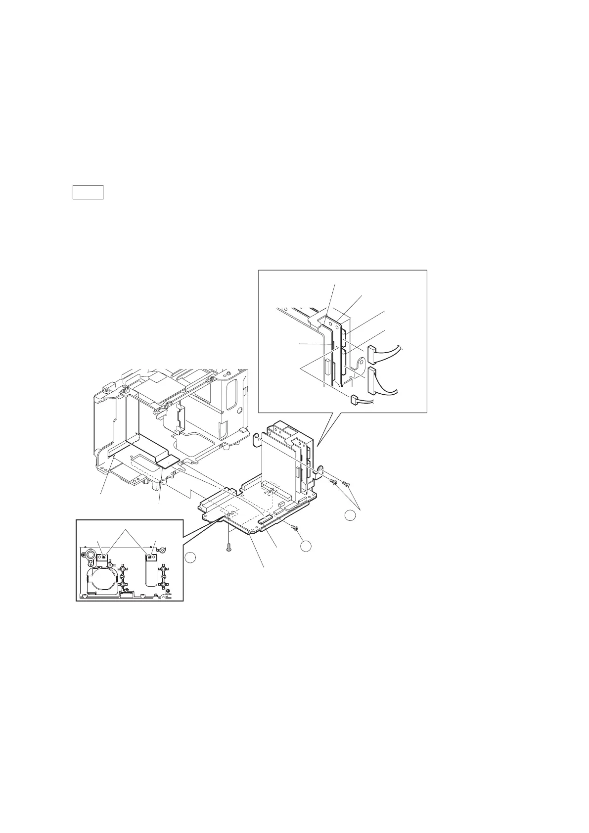
Procedure
1. Disconnect the harness from the connector CN202 on the RE-298 board.
2. Disconnect the harnesses from the connectors CN100 and CN101 on the RE-299 board.
3. Remove the five precision screws (M2 x 4).
Note
When installing these precision screws, push the U groove of the bracket AU against the positioning pin, and tighten
the screws in the order of numbers shown in the figure.
4. Disconnect the HN-386 board from the connector CN104 on the AU-342 board.
5. Disconnect the AU-342 board from the connector CN2400 on the DPR-343 board.
Positioning pins
U groove
U groove
1
2
3
Precision screws
(M2 x 4)
Precision screw
(M2 x 4)
Precision screws
(M2 x 4)
CN104
CN100
CN202
CN101
AU-342board
HN-386 board
CN2400
(DPR-343 board)
RE-299 board
RE-298 board
6. Remove the precision screws (M2 x 4).
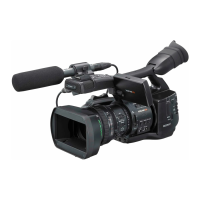
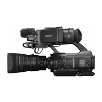
PMW-200/PMW-EX280
2-49