62
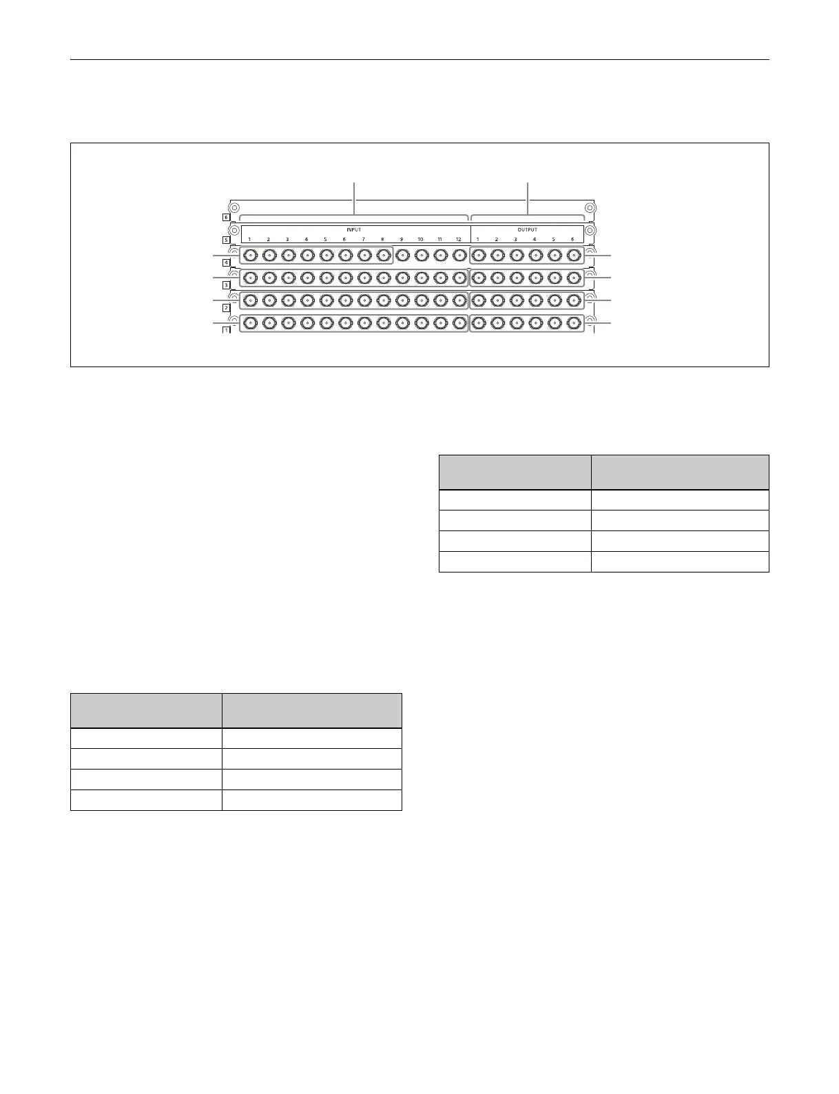
Input Connectors and Output Connectors
Input/output connector numbers
Input/output connector numbers are assigned from left to
right on the 1st, 2nd, 3rd, and 4th connector boards in that
order.
Input/output connectors on the 3rd and 4th connector
boards
can be used when XKS-G1110 Additional I/O
Boards (option) are installed.
When the system signal format is 2160P, only the input/
ou
tput connectors on the 1st and 2nd connector boards
can be used.
4K signal input/output connector
assignment
Transfer of subdivided-by-4 image (sub images)
as four separate signals
A 4K signal is assigned as a group of four connectors.
The assignment is as follows.
The connector numbers correspond to sub images 1, 2, 3,
and
4 in that order.
The input and output settings are speci
fied using the first
number in each group.
Transfer of 4K signal as a single signal
A 4K signal is assigned to a single connector.
The assignment is as follows.
SDI output connector disable setting
SDI output connectors can be enabled/disabled. When
disabled, no signal is output from the output connector.
If a cable is not connected to a
n enabled output connector,
radio wave interference may occur. Disable unused
output connectors.
For details, see “Enabling/Disabling an SDI Output
Connector” (page 378).
INPUT OUTPUT
Row 4 (INPUT 37 to 44)
Row 3 (INPUT 25 to 36)
Row 2 (INPUT 13 to 24)
Row 1 (INPUT 1 to 12)
Row 4 (OUTPUT 19 to 24)
Row 3 (OUTPUT 13 to 18)
Row 2 (OUTPUT 7 to 12)
Row 1 (OUTPUT 1 to 6)
4K format input signal/
output signal
Connector number
1st system 1, 2, 3, 4
2nd system 5, 6, 7, 8
3rd system 9, 10, 11, 12
(and so on) (and so on)
4K format input signal/
output signal
Connector number
1st system 1
2nd system 2
3rd system 3
(and so on) (and so on)

 Loading...


