82
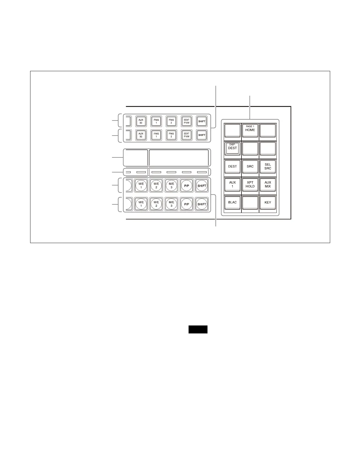
ICP-X7000 AUX bus control block (AUX bus operation mode)
The number of buttons in a b
utton row varies depending
on the modules used.
• MKS-X7017: 36 buttons
• MKS-X7018: 28 buttons
• MKS-X7019: 20 buttons
The illustration below shows a 36-button AUX bus
co
ntrol block (AUX bus operation mode).
Cross-point buttons
The button numbers are labeled on the cross-point buttons
of the cross-point control block/AUX bus control block.
Signals are assigned for each
button number and you
select signals by pressing the buttons.
For details about assign
ing signals, see “Creating a
Cross-Point Assign Table” (page 379).
Shift button
A shift button is assigned to the rightmost button of each
cross-point button row.
You use the shift button to swit
ch between the button
number in the shifted state and the button number in the
unshifted state in the button row.
The shift button has two operation modes.
Hold mode: Mode where the shifted sta
te is selected
while the button is pressed
Lock mode: Mode where every time the button is pressed,
i
t toggles between the shifted state and unshifted state
You can also disable the shift button func
tion.
For details, see “Setting the Shift Button” (page 380).
Delegation button row shift button
In an AUX bus control block, the shift button in
deleg
ation button rows (1st row/2nd row) can also be
used.
A shift button is assigned to th
e rightmost button and can
be set to hold mode or lock mode.
For details, see “Setting the operation
mode of the shift
button” (page 404).
The shift button cannot be used in a delegation button row
(1
st row) on a cross-point control block in key/AUX bus
delegation mode.
Re-entry buttons
You can assign re-entry signals to the cross-point button
rows of the cross-point control block/AUX bus control
block for use as re-entry buttons.
Re-entry buttons are used to load
an image created on one
switcher bank as an input signal on another switcher
bank.
Delegation button rows
Display
Cross-point indicators
Cross-point pad
1st row
2nd row
3rd row
4th row
Cross-point button rows
Note