Do you have a question about the Starlite MK5 and is the answer not in the manual?
Provides essential information for operating and servicing the Starlite Mk 5 unit.
Indicates the specific version of the User/Service Manual provided.
Details copyright ownership and patent information for the Starlite Mk 5.
Lists trademarks and registered names associated with the Starlite Mk 5.
Provides contact details for authorized distributors of the Starlite Mk 5.
Essential guidelines for safely handling the Starlite Mk 5 unit during operation and transport.
Lists the EMC, LVD, and safety standards the Starlite Mk 5 conforms to.
Details electrical safety tests required for the unit, including bonding and insulation.
Information on ongoing product improvements and how to provide customer feedback.
Explains the manual's content and how unit modifications are documented.
Details pan, tilt, focus, iris, gobos, CMY, colour wheel, and prism functionalities.
Covers prism, frost, shutter, and dimmer functionalities.
Details lamp type, power supply, cooling, mechanical design, and protocol.
Lists general safety precautions and warnings for operating the Starlite Mk 5.
Key safety and power connection checks before operating the unit.
Guidance on DMX data connections and potential issues.
Lists the factory default DMX channel assignments and their functions.
Advice on saving shipping materials and using approved flightcases.
Instructions for making correct electrical connections and ensuring proper grounding.
Details on power supply requirements, circuit protection, and surge current.
Hints for programmers unfamiliar with moving head units.
Procedures for safely starting and shutting down the Starlite Mk 5 system.
Provides the physical dimensions and weight of the Starlite Mk 5 unit.
Illustrates the M10 threaded fixing points on the unit base for mounting.
Information on using safety wires and available rigging points.
Specifies required spacing for rigging and clearance from combustible materials.
Table detailing voltage, frequency, current, and power consumption.
Specifies compatible lamp types and required fuse ratings.
Details operating temperature, humidity, altitude, and IP rating.
Information on DMX512 protocol, XLR connectors, and daisychaining.
Explains the need for DMX termination and maximum channel requirements.
Details the default DMX channel assignments and their corresponding unit functions.
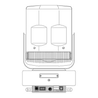
Overview of the base unit's internal components and external connectors.
Explanation of the status LEDs and their indication of unit conditions.
Instructions on how to adjust the DC supply voltage selector switch.
Details settings for magnetic ballast models, including frequency taps.
Information on voltage/frequency settings for electronic ballast models.
Details the yoke assembly and location of the tilt position sensor.
Overview of the head assembly and how to access the fan module.
Procedure for accessing fan module, card retainer, and other components.
Diagram identifying all numbered components within the head assembly.
Steps to remove the motherboard for access to drive cards.
Details the lamp housing, its cooling fins, and heat generation.
Step-by-step instructions for safely replacing the unit's lamp.
Explanation of the rotary switches used for setting the DMX start address.
Instructions on how to activate and use the unit's self-test mode.
Details the function of the DIP switches on the drive cards for personality and address.
Table mapping drive card positions to function names and binary/DMX addresses.
Guidance on setting function addresses and internal DMX addresses for drive cards.
Diagram showing motherboard layout, slots, and connector positions for drive cards.
Identification of components on the front side of the base PCB.
Explains the function of the two-way switches and their relation to status LEDs.
Details transformer, rectification circuits, fuses, and DC voltage components.
Describes ignitor, PFC capacitors (magnetic) or SMPSU (electronic) on the PSU side.
Instructions for performing general maintenance and cleaning of the unit's exterior.
Step-by-step guide for removing head modules and internal components.
Procedure for removing the CMY colour fading module.
Procedure for removing the prism module from the head assembly.
Instructions for lubricating and cleaning rotating gobo gears.
Guidance on cleaning colour filters, triplet lens, and prism surfaces.
Procedure for cleaning the prism module and its associated blades.
Steps for removing and installing rotating gobos.
Procedure for removing and replacing colour wheel dichroic filters.
Procedure for setting the reference voltage for pan and tilt positioning.
Guide to adjusting the pan position sensor on earlier models.
Detailed steps for adjusting the pan sensor unit and its meshing.
Guide to adjusting the pan position sensor on current models.
Further steps for adjusting the pan sensor, ensuring correct backlash.
Information regarding adjustments to the pan gearbox and clutch assembly.
Instructions for setting the tilt to its mid position and adjusting the sensor.
Procedure for adjusting tilt gearbox backlash to regain optimum performance.
Steps for setting drive card gain and torque pots for stable operation.
Overview of common problems and how to approach diagnosis and repair.
Provides contact methods for obtaining technical support from Starlite.
Lists common issues with possible causes and recommended remedies.
Addresses problems like dimming, non-responsiveness, and incorrect movement.
Troubleshooting for head functions, gobos, colour wheels, and iris.
Specifies the essential tools needed for maintenance and repair.
Details the requirements for a multimeter used for testing.
Details the warranty period, coverage, and responsibilities for claims.
Form for users to submit notes, comments, or problems for product improvement.