STARLITE Mk5 User Manual Version 1.2
26
Unit review
Base of the unit
The base contains the power supply for the lamp, logic and drive functions, power and data
connectors and status indicators.
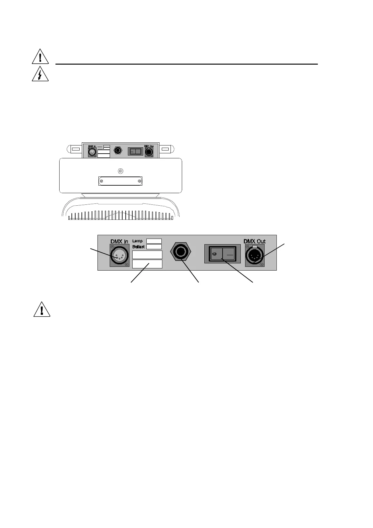
Connector Panel
The connector panel is located in the base of
the unit and contains the power-input cable, data
connectors and the circuit breaker/power switch.
Status Indicator Panel
On the front base cover there is a panel with five LED’s recessed behind it. These LED’s indicate
various unit conditions. There are 4 red LED’s marked 1 to 4 and 1 green. The green LED signifies
the DMX Data Status. The green LED should remain lit when there is no DMX signal present. When
a valid DMX signal is applied, the green LED will extinguish. Status LED’s 1 to 4 show the lamp,
interlock and switch states and should not be lit after the lamp has struck or during normal use.
For more information, please refer to section ”2 way Switch”
5-Way chassis female XLR
connector for DMX thro’
output
5-Way chassis male XLR
connector for DMX input
Power switchPower cableSpecification