STARLITE Mk5 User Manual Version 1.2
41
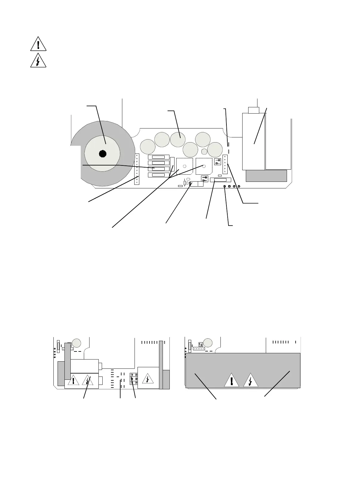
Rear (DC Supply) Side of Base
This side of the base contains the transformer, rectification circuits and fuses which supply and protect
the DC Voltages used by the motors, logic circuits etc.
STARLITE Mk5 BASE PCB (Issue 3)
Lamp PSU Side of the Base
This area of the base contains either;
(1) the Ignitor and PFC capacitors in magnetic ballast models
or,
(2) the SMPSU in electronic ballast models.
CAUTION: This section of the base has EXPOSED LIVE PARTS and LETHAL VOLTAGES
and ENERGIES present. Ensure the unit is switched OFF and DISCONNECTED from the
mains supply BEFORE working in this area.
In magnetic ballast models, this area also contains the two different frequency taps for the ballast.
See “Setting the Starlite Mk5 unit Voltage”
Toroidial
transformer
DC smoothing
capacitors
PFC capacitors
(Magnetic ballast
Transformer
connector
Earth/0 Volt(DC)
6 Way “power”
loom connector
Supply fuses.
2.5A (T) pan/tilt
2.5A (T) pan/tilt
10A. (T) +12 Volts
6.3A (T) +24 Volts
Bridge rectifiers x 3
(2 mounted above)
Test points for
+ 5 Volts fuse
2 A (T)
+5 V regulator
(on heatsink)
PFC capacitors Connections
Ignitor
Switch-Mode PSU.
(Type varies with