STARLITE Mk5 User Manual Version 1.2
29
The Yoke
The yoke is secured to the pan ring gear and provides the routing, from the static base to the moving
head, for the various wiring looms. Also located on the yoke assembly is the tilt position sensor, which
can be accessed by removing the plastic cover (See “Adjusting Tilt Position Sensor”) if
adjustment/resetting is required.
The Head
The head contains the lamp housing, tilt motor, function modules, decoder and function drive cards
and the head cooling system. To gain access inside the head it is necessary to remove one (or both) of
the head covers by undoing the two ¼ turn fasteners on each cover.
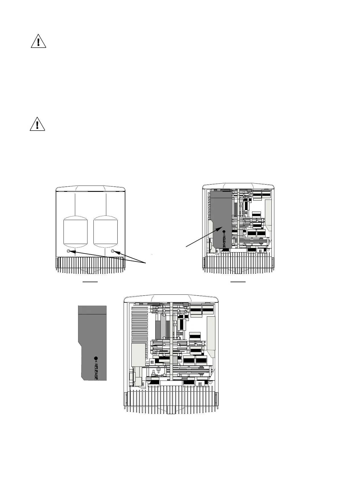
“Fan” Side of the Head (Earlier models)
With pan in its mid (neutral) position, removing the cover on the cable/connector side, will give you
access to secondary fan module, some of the cards below it and allow the changing of gobos etc. The
fan module is removed by undoing the ¼ turn fastener located thru the “Release” hole and unplugging
the fan module (if necessary).
When replacing the fan module/card retainer ensure that you re-plug the fan power
connector.
Step 1 Step 2
¼ turn fasteners
Recessed ¼ turn
fastener on fan