STARLITE Mk5 User Manual Version 1.2
38
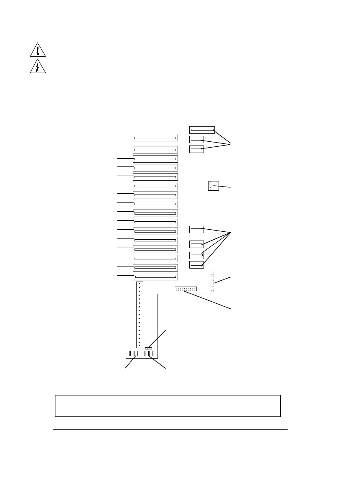
Drive card motherboard positions
The motherboard, which is located in the head of the unit, has 15 drive card slots and one decoder
card slot. The connector which is nearest to the front of the lamp head is for the decoder card and slots
1 to 15 are for the drive cards. These 15 slots correspond to the various functions function positions
and are allocated as follows:
STARLITE Mk 5 Motherboard (Issue 3)
Please do not attempt to remove the drive cards whilst the unit is powered up.
Focus unit connector
(on underside of PCB)
Gobo/Colour wheel module
connector
Gobo/Iris module
connector
(on underside of PCB)
16 way cable loom
connector
4 way connector
(Safety/Interlock)
Edge connector sockets
for X-fade/Shutter module
Edge connector socket
for front module
+ve Head fan supply ( x 3)
-ve Head fan supply ( x 3)
(1) Prism rotate card
(2) Prism select card
(3) Frost card
(4) Dimmer card
(5) Focus card
(6) Gobo wheel 2 card
(7) Gobo rotate 2 card
(8) Colour wheel card
(9) Gobo wheel 1 card
(10) Magenta card
(11) Cyan card
(12) Yellow card
(13) Shutter card
(14) Iris card
(15) Gobo rotate 1 card
N.B. In current models the head fan and Safety/Interlock connections
are combined in one 8-way connector.