STARLITE Mk5 User Manual Version 1.2
39
Unit Review (cont.)
Front (Indicator) Side of the Base
After ensuring the unit is switched off and disconnected from its power source, remove the three hex
screws, one on the front of the lamp and one on each side, and gently pull the cover away from the
lamp base.
Note: There are two hex screws on each side of lamp, but only one may be removed from each side,
the others are captive.
If required, you can now unclip the cover safety wire and disconnect the screening cable.
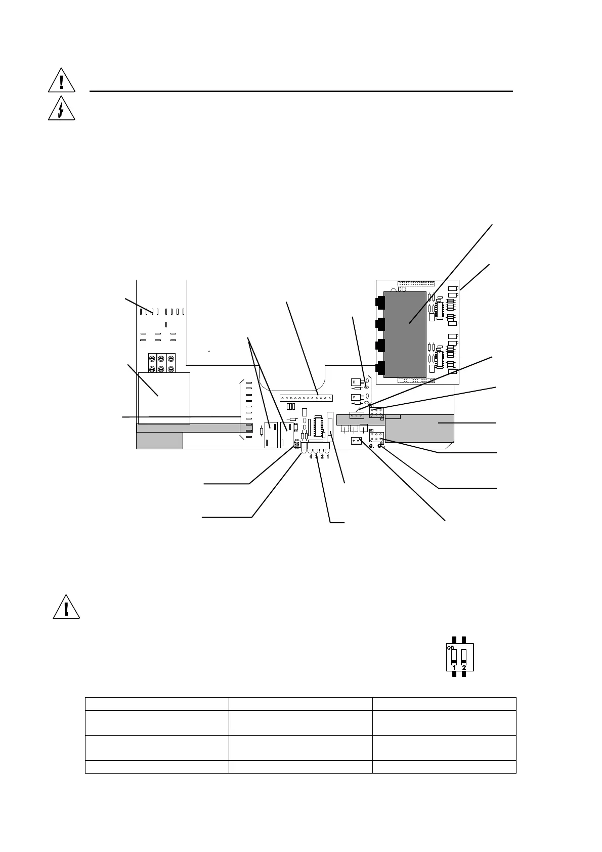
STARLITE Mk5 BASE PCB
(Issue 3)
2 Way Switch
There are two switches located between the lamp power PSU relays and the status
LED’s. Switch 1 is used to disable the 2 minute time-out when a DMX signal is
removed and switch 2 is used to inhibit the lamp strike during testing. The normal
status for these switches is as follows:
Switch Status Switch 1 Switch 2
Lamp Strike Enabled
2 minute time out Enabled
Off On
Lamp Strike Enabled
2 minute time-out Disabled
On On
Lamp Strike Disabled N/A Off
Ballast/Ignitor
connections
(Magnetic ballast
models only)
Ignitor
(Magnetic ballast
models only)
Earth (Ground)
connections
12 way “signal” loom
(to head)
Lamp
PSU
+/- 15 Volt
regulators
Pan/Tilt
drive card
Tilt unit
connector
Base fan
Pan Unit
Connector
2 Way Switch
See below
Green LED
(DMX Status)
See below
Red Status LED’s
See Below
Fan Supply
Test Points
Fan Supply
(to Head)
Fan Fuse
2 A (T)
DMX Input
(from I/P XLR’s)
+/- 15 V, +/-36
V and 0 Volt
Test points
(under pan/tilt
card)