STARLITE Mk5 User Manual Version 1.2
28
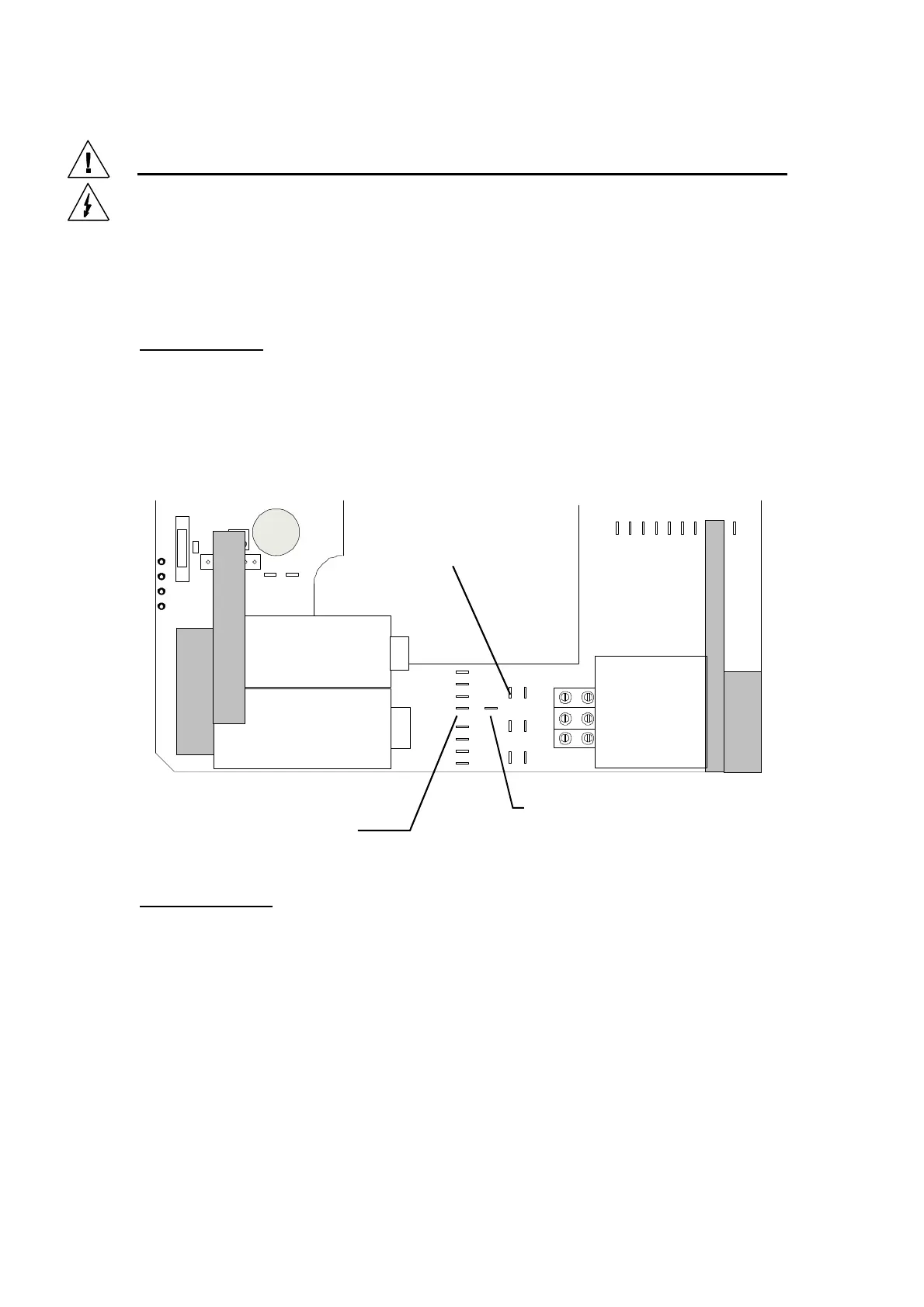
Lamp Ballast Voltage/Frequency Selection
Magnetic Ballast Version
CAUTION: This section of the base has EXPOSED LIVE PARTS
and LETHAL VOLTAGES and ENERGIES present. Ensure the unit
is switched OFF and DISCONNECTED from the mains supply
BEFORE working in this area.
Earlier Models:
There is a 50 / 60 Hertz tap for the magnetic ballast supply located between the power factor
correction capacitors and the lamp ignitor. These are either (1)¼ inch spade connectors or, (2)
soldered connections, with the Red wire being 50 Hertz and the White wire, 60 Hertz. The unused tap
should be moved onto the ‘SPARE BALLAST TAP’ terminal and the selected tap applied to the
terminal marked ‘TO BALLAST’ on the 4 way ‘LIVE’ block. Care should be taken to ensure the
correct settings are applied for the location.
Current Models:
On the latest models, although the wiring is basically the same, all of the connections have been
changed to PCB mounted screw terminals.
Electronic Ballast Version
The Switch-Mode Power Supplies fitted to both the 575 W and the 1200 W versions do not require
adjustment when used within the specified Voltage/Frequency limits.
i.e. 95-130 and 200-250 Volts, 47-65 Hz
“Spare Ballast Tap”
Isolated Terminal
“To Ballast”
Connection
Red Wire = 50 Hz
Ballast/Ignitor
Connection