DocID018909 Rev 11 485/1731
RM0090 LCD-TFT Controller (LTDC)
511
Reload Shadow registers
Some configuration registers are shadowed. The shadow registers values can be reloaded
immediately to the active registers when writing to these registers or at the beginning of the
vertical blanking period following the configuration in the LTDC_SRCR register. If the
immediate reload configuration is selected, the reload should be only activated when all new
registers have been written.
The shadow registers should not be modified again before the reload has been done.
Reading from the shadow registers returns the actual active value. The new written value
can only be read after the reload has taken place.
A register reload interrupt can be generated if enabled in the LTDC_IER register.
The shadowed registers are all the Layer 1 and Layer 2 registers except the
LTDC_LxCLUTWR register.
Interrupt generation event
Refer to Section 16.5: LTDC interrupts for interrupt configuration.
16.4.2 Layer programmable parameters
Up to two layers can be enabled, disabled and configured separately. The layer display
order is fixed and it is bottom up. If two layers are enabled, the Layer2 is the top displayed
window.
Windowing
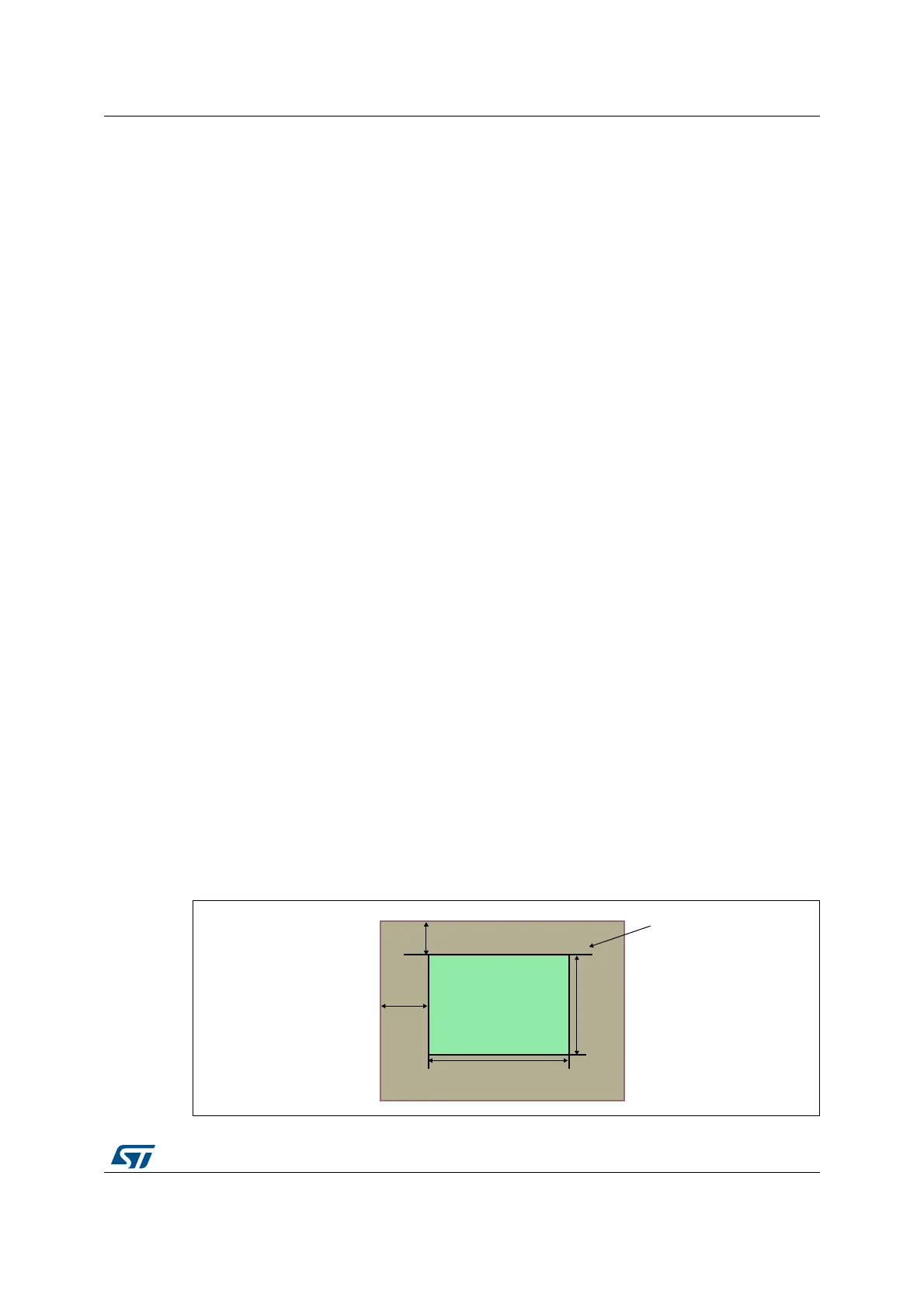
Every layer can be positioned and resized and it must be inside the Active Display area.
The window position and size are configured through the top-left and bottom-right X/Y
positions and the Internal timing generator which includes the synchronous, back porch size
and the active data area. Refer to LTDC_LxWHPCR and LTDC_WVPCR registers.
The programmable layer position and size defines the first/last visible pixel of a line and the
first/last visible line in the window. It allows to display either the full image frame or only a
part of the image frame. Refer to Figure 83
• The first and the last visible pixel in the layer are set by configuring the WHSTPOS[11:0]
and WHSPPOS[11:0] in the LTDC_LxWHPCR register.
• The first and the last visible lines in the layer are set by configuring the WHSTPOS[10:0]
and WHSPPOS[10:0] in the LTDC_LxWVPCR register.
Figure 83. Layer window programmable parameters:
$FWLYH'DWD$UHD
:963326ELWVLQ
/7'&B/[:+3&5
/D\HU
:LQG R Z
:LQGRZ
069
:+63326ELWVLQ
/7'&B/[:+3&5
:+67326ELWVLQ
/7'&B/[:+3&5
:967326ELWVLQ
/7'&B/[:+3&5

 Loading...