DocID018909 Rev 11 489/1731
RM0090 LCD-TFT Controller (LTDC)
511
Default color
Every layer can have a default color in the format ARGB which is used outside the defined
layer window or when a layer is disabled.
The default color is configured through the LTDC_LxDCCR register.
The blending is always performed between the two layers even when a layer is disabled. To
avoid displaying the default color when a layer is disabled, keep the blending factors of this
layer in the LTDC_LxBFCR register to their reset value.
Color Keying
A color key (RGB) can be configured to be representative for a transparent pixel.
If the Color Keying is enabled, the current pixels (after format conversion and before
blending) are compared to the color key. If they match for the programmed RGB value, all
channels (ARGB) of that pixel are set to 0.
The Color Key value can be configured and used at run-time to replace the pixel RGB value.
The Color Keying is enabled through the LTDC_LxCKCR register.
16.5 LTDC interrupts
The LTDC provides four maskable interrupts logically ORed to two interrupt vectors.
The interrupt sources can be enabled or disabled separately through the LTDC_IER
register. Setting the appropriate mask bit to 1 enables the corresponding interrupt.
The two interrupts are generated on the following events:
• Line interrupt: generated when a programmed line is reached. The line interrupt
position is programmed in the LTDC_LIPCR register
• Register Reload interrupt: generated when the shadow registers reload was performed
during the vertical blanking period
• FIFO Underrun interrupt: generated when a pixel is requested from an empty layer
FIFO
• Transfer Error interrupt: generated when an AHB bus error occurs during data transfer
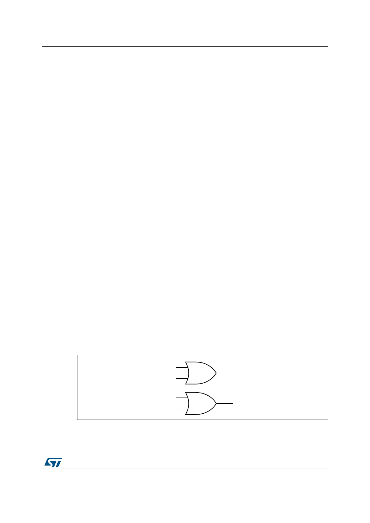
Those interrupts events are connected to the NVIC controller as described in the figure
below.
Figure 85. Interrupt events
/LQH
5HJLVWHU5HORDG
/7'&JOREDOLQWHUUXSW
069
),)28QGHUUXQ
7UDQVIHUHUURU
/7'&JOREDO(UURULQWHUUXSW