Serial peripheral interface (SPI) RM0090
912/1731 DocID018909 Rev 11
28.5.3 SPI status register (SPI_SR)
Address offset: 0x08
Reset value: 0x0002
Bit 2 SSOE: SS output enable
0: SS output is disabled in master mode and the cell can work in multimaster configuration
1: SS output is enabled in master mode and when the cell is enabled. The cell cannot work
in a multimaster environment.
Note: This bit is not used in I
2
S mode and SPI TI mode.
Bit 1 TXDMAEN: Tx buffer DMA enable
When this bit is set, the DMA request is made whenever the TXE flag is set.
0: Tx buffer DMA disabled
1: Tx buffer DMA enabled
Bit 0 RXDMAEN: Rx buffer DMA enable
When this bit is set, the DMA request is made whenever the RXNE flag is set.
0: Rx buffer DMA disabled
1: Rx buffer DMA enabled
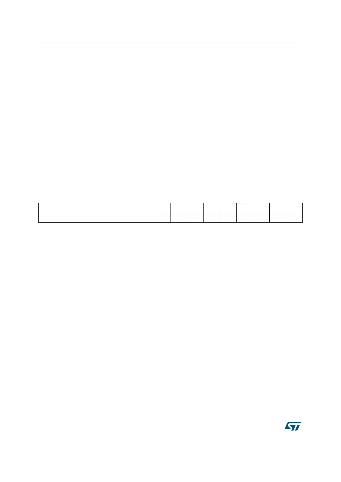
15 14 13 12 11 10 9 8 7 6 5 4 3 2 1 0
Reserved
FRE BSY OVR MODF
CRC
ERR
UDR
CHSID
E
TXE RXNE
r r r r rc_w0 r r r r
Bits 15:9 Reserved. Forced to 0 by hardware.
Bit 8 FRE: Frame format error
0: No frame format error
1: A frame format error occurred
This flag is set by hardware and cleared by software when the SPIx_SR register is read.
Note: This flag is used when the SPI operates in TI slave mode or I2S slave mode (refer to
Section 28.3.10).
Bit 7 BSY: Busy flag
0: SPI (or I2S) not busy
1: SPI (or I2S) is busy in communication or Tx buffer is not empty
This flag is set and cleared by hardware.
Note: BSY flag must be used with caution: refer to Section 28.3.7: Status flags and
Section 28.3.8: Disabling the SPI.
Bit 6 OVR: Overrun flag
0: No overrun occurred
1: Overrun occurred
This flag is set by hardware and reset by a software sequence. Refer to Section 28.4.8 on
page 907 for the software sequence.
Bit 5 MODF: Mode fault
0: No mode fault occurred
1: Mode fault occurred
This flag is set by hardware and reset by a software sequence. Refer to Section 28.3.10 on
page 889 for the software sequence.
Note: This bit is not used in I
2
S mode
 Loading...