1-25
Power and Alarm Wiring
Overview
DC voltage in the range of 10 to 30 VDC (3.0W) needs to be applied between the P1 (plus)
terminal and the Minus terminal as shown below. To maintain a UL 508 panel listing use a
Class 2 power supply. The chassis screw terminal should be tied to panel or chassis ground. To
reduce down time resulting from power loss, these industrial Ethernet switches can be powered
redundantly with a second power supply as shown below.
NOTE: When powering multiple switches from a common power supply, it is most reliable to power the switches
sequentially rather than simultaneously. The characteristics of the power supply and the significant startup current of the
switches may result in an error in booting the switches when powered simultaneously.
Screw Torque
When tightening the screws be careful to tighten to a max. torque of 5 lb-in [0.57 Nm]. Wire
size should be between 24 AWG and 12 AWG.
Before performing any wiring to these switches make sure...
• The area is currently nonhazardous (especially when working in Class 1, Div 2 or Zone 2
hazardous locations).
• Power is off to the switch
• The screw terminal block is unplugged. This is especially important on the aluminum housed
units as shown below. Connecting or disconnecting wires to the screw block when its in place
and power is turned on can allow the screwdriver to short the power to the case
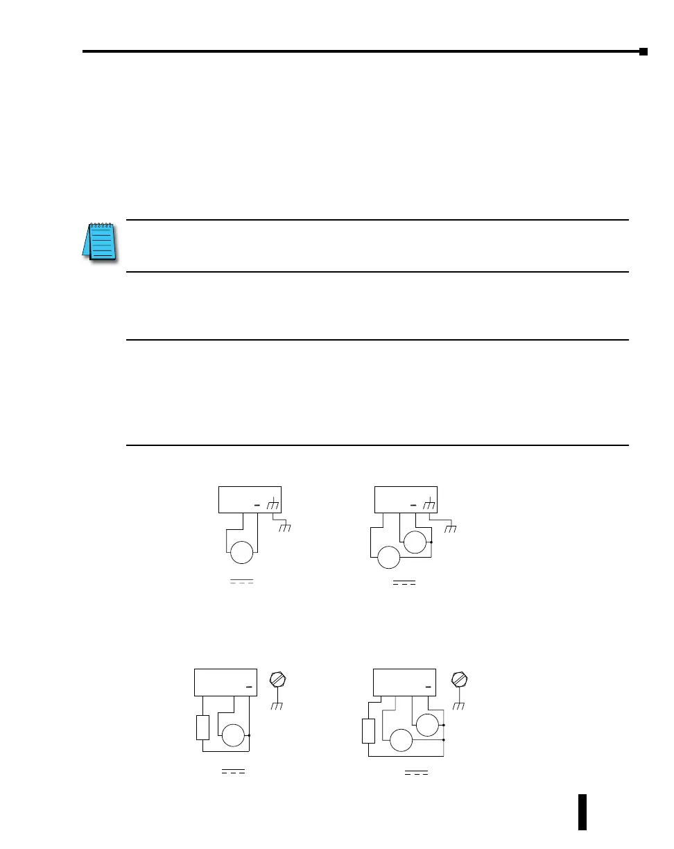
Unmanaged Models:
One DC Supply
+
–
P2 P1
Single DC Power
Redundant DC Power
Chassis
GND
(panel)
+
–
+
–
Chassis
GND
(panel)
Dual DC Supplies
P2 P1
Managed Models:
SE-SW5M, SE-SW5M-2ST, SE-SW5M-2SC, SE-SW8M, SE-SW8M-2ST and
SE-SW8M-2SC
OK P2
One DC Supply
+
–
Chassis
GND
(panel)
P1
Chassis
GND
(panel)
Single DC Power Redundant DC Power
+
–
+
–
Dual DC Supplies
OK P2
P1
+
–
+
–
Alarm
Output
Load
(opt.)
Alarm
Output
Load
(opt.)
Chapter 1 - Hardware
Stride Industrial Ethernet Switches User Manual 2nd Ed. Rev. B