64 6086-009-001 REV B www.stryker.com
Return To Table of Contents
Service Information
BACKREST ADJUSTMENT
Tools Required:
• 1/2” Combination Wrench
• 5/32” Hex Wrench
• 3/32” Hex Wrench
• Small Slotted Screwdriver
Procedure:
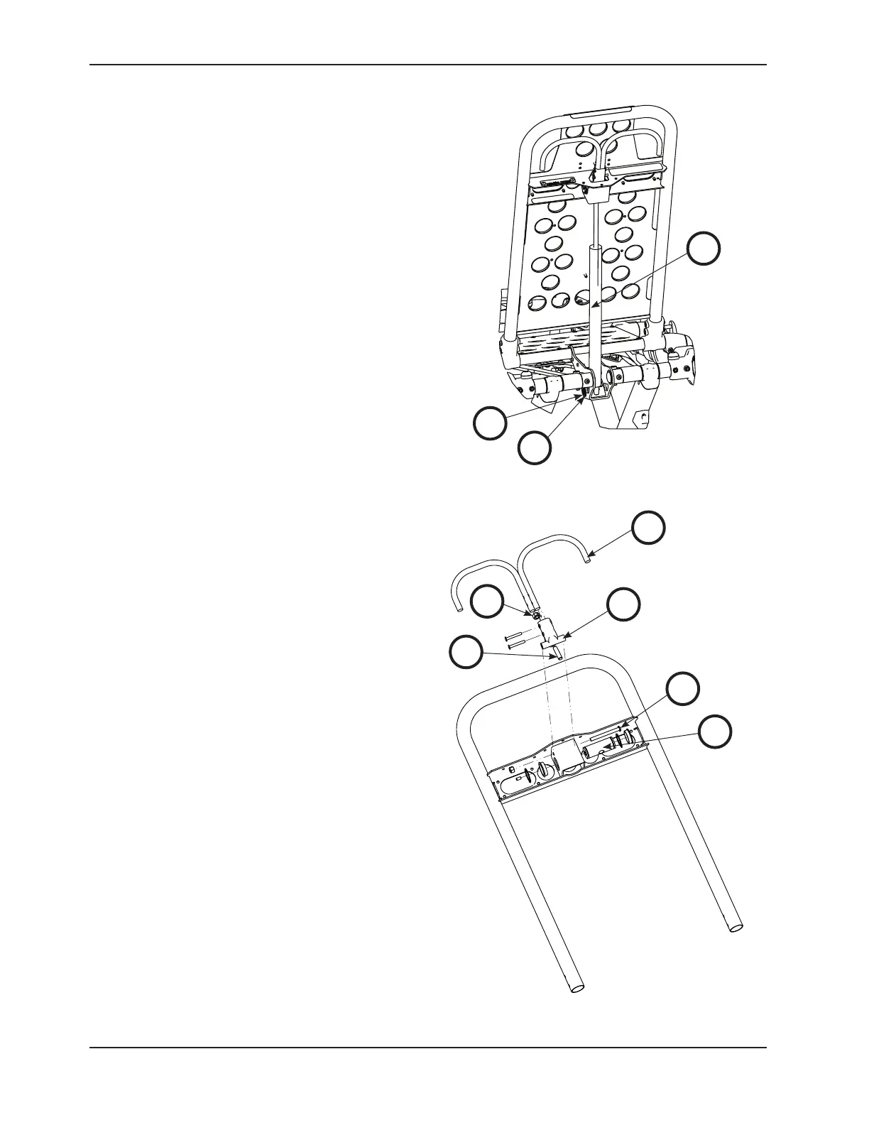
1. For easier access, move the backrest to 73 degrees.
Note: Before continuing with the backrest adjustment
procedure, be sure that the cylinder (A) is completely
threaded into the yoke (B) so no threads are showing
on the shaft of the cylinder. If threads are showing,
use a 3/32” hex wrench to remove the set screw
(C) in the center of the yoke. Using a small slotted
screwdriver, remove the E-clip and pin (D & E) that
holds the bottom of the pneumatic cylinder. Thread
the cylinder shaft (A) completely into the yoke (B).
Replace the E-clip and pin (D & E) and replace the
set screw (C) using Loctite
®
. (Figure 61 and Figure
62)
2. Using a 1/2” combination wrench, loosen the hex nut
(F) on the backrest pivot (J) while holding the set
screw (H) fixed in the pivot (Figure 62).
3. Using a 5/32” hex wrench, turn the set screw (H) until
there is no play between the backrest release handle
(K) and the pneumatic cylinder release button (Figure
62).
Note: Make sure that the backrest travels from flat to
at least 73 degrees. If it does not, turn the set screw
clockwise 1/2 turn. Repeat until at least 73 degrees
of travel is achieved.
4. Lower the backrest to a 5−10 degree angle and release
the handle. Apply approximately 50 lb of downward
force to the end of the backrest. If the backrest drifts
down, turn the set screw counterclockwise. Repeat
until the backrest does not drift downward.
5. Using the 1/2” combination wrench, tighten the hex
nut (F) while holding the set screw fixed in the pivot
(Figure 62).
6. Verify proper operation of the unit before returning it
to service.
B
A
D
E
Figure 62
K
C
H
F
J
Figure 61