68 6086-009-001 REV B www.stryker.com
Return To Table of Contents
Service Information
HEADSECTION REPLACEMENT
Tools Required:
• 7/16” Combination Wrench
• 3/16” Hex Wrench
Procedure:
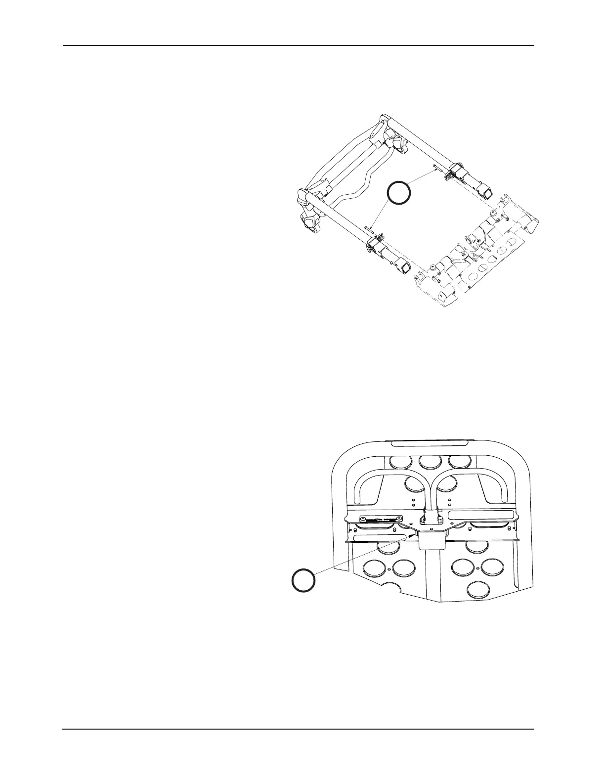
1. Raise the cot and the backrest to the full upright
position.
2. Using a 7/16” combination wrench and a 3/16” hex
wrench, remove the two screws (A) that secure the
cap bearings to the base litter interface bracket
(one on each side) (Figure 66).
3. Squeeze the head release handles and slowly
remove the head section assembly.
4. Reverse steps to reinstall.
5. Verify proper operation of the unit before returning
it to service.
BACKREST GAS CYLINDER REPLACEMENT
Tools Required:
• 3/32” Hex Wrench
• Slotted Screwdriver
Procedure:
1. Raise the cot and the backrest to the full upright
position.
2. Using a 3/32” hex wrench, loosen the set screw
(A) that holds the gas shaft to the yoke (Figure 67).
3. Using a slotted screwdriver, remove the e-clip from
the clevis pin that secures the bottom of the gas
cylinder.
4. Unscrew the gas cylinder shaft from the yoke.
5. Reverse the above procedures to install the new
gas cylinder. See “Backrest Adjustment” on page
64.
6. Verify proper operation of the unit before returning
it to service.
Figure 66
A
A
Figure 67