www.stryker.com 6086-009-001 REV B 65
Return To Table of Contents
WHEEL LOCKING FORCE ADJUSTMENT
Tools Required:
• 5/32” Hex Wrench
• 7/16” Combination Wrench or Socket
Procedure:
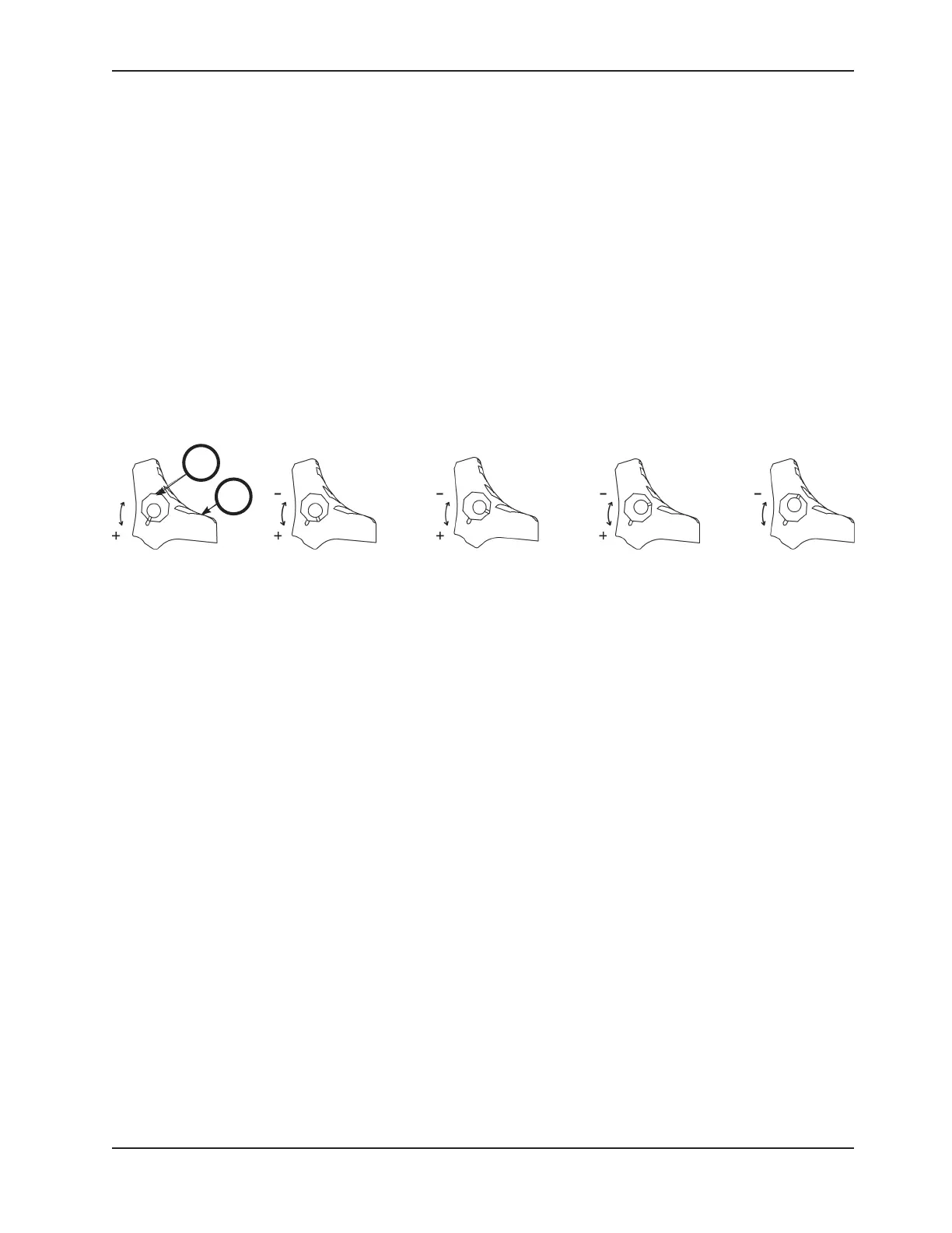
1. Using the 5/32” hex wrench and 7/16” combination wrench or socket, remove the socket screw from the center of
the lock pedal. The wheel lock is initially assembled with the pedal set at the minimum locking force. The marker
on the pedal (A) is aligned with the marker on the octagonal sleeve (B) (Figure 63).
2. Remove the sleeve (B). Rotate the sleeve counterclockwise to increase the pedal locking force and clockwise to
decrease the locking force. Insert the sleeve into the pedal (Figure 63).
3. Using the 5/32” hex wrench and 7/16” combination wrench or socket, reinstall the socket screw.
4. Test the pedal locking force and verify that the pedal holds properly before returning it to service.
Service Information
Figure 63: Wheel Locking Force Adjustment
MINIMUM
MAXIMUM
B
A